Easy Vibe: How Good Can We Make It?

Big Monk

Well-known member
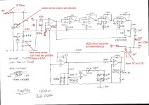
Been interested lately in playing with the Easy Vibe:
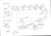
EasyVibe.jpeg

I like the idea of the Easy Vibe. It’s a simpler PCB than an LDR/Bulb Univibe and seems easy to dial in.

I’ve heard that green LEDs have light signature for most LDRs and it seems like a wider range of LDRs could be adapted.

There is also the R.G. Keen Ramp LFO as well:
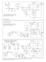
IMG_0882.jpeg

Let’s discuss….
 
I’ve always seen the LED/LDR optocouplers. Has somebody tried a phototransistor optocoupler, like the 4N25?
I see those readily available and always wondered if they can be used for the same purpose…
 
Last edited:
I've got a Wilson Effects Haze Drive. I think it's based on the Easy Vibe--I don't know if it's straight copy of Hollis's circuit or if it's been tweaked.
If you're interested I can crack it open and get a picture.
 
I've got a Wilson Effects Haze Drive. I think it's based on the Easy Vibe--I don't know if it's straight copy of Hollis's circuit or if it's been tweaked.
If you're interested I can crack it open and get a picture.

That would be awesome.
 
I’ve always seen the LED/LDR optocouplers. Has somebody tried a phototransistor optocoupler, like the 4N25?
I see those readily available and always wondered if they can be used for the same purpose…

The main phototransistor that I see getting used in place of LDRs in audio stuff are the H11F(X)M optofets, which are available for $3/pop now but have had some availability issues in the past. Ray Ring has some cool designs using them, including some compressors. Seems like using 4 would start to get complicated (and not to mention expensive). Probably the easiest implementation would be with a quad VCF like the as3320 or a quad VCA like the 2164. Ex https://www.njohnson.co.uk/index.php?menu=2&submenu=0&subsubmenu=3 and then staggering to match a unvibe
 
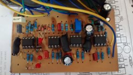
IMG_20230819_134643413_HDR.jpg


The 4 LDRs are shrinkwrapped with LEDs.

The ICs are TL072. The big electrolytics are 470uF. The short one is 100uF and the skinny one is 1u.
The white box cap is 1n.

The 3 poly caps are 153, 224, and 471 (15n, 220n, and 470pf). The blue box one is 4n7.

I'm not really sure what that silver thing that looks kind of like a box cap is. The lettering on it says "10Q HT".

Overall, it looks close to stock.
 
Last edited:
re silver thing — what came to my mind was a crystal.

A crystal in a vibe? Ridonkulus!

I searched the Net for "10Q HT" with various other added search terms such as "through-hole" , "pin-spacing" , and others and came up with nada.


Maybe it's a McGuffin.

Any new info on what it might be?
 
When I built it (2014), I made some modifications that I found on the internet. The problem I had with this pedal was that it made noise when I turned it on and off, and when I set the volume to zero, I could hear the oscillation of the optocouplers as a clock-like noise.

The circuit does not have a pulldown resistor, would adding a buffer and a pulldown resistor solve the impedance and noise problems?


1717608491094.jpeg
1717608631716.jpeg
 
View attachment 54878


The 4 LDRs are shrinkwrapped with LEDs.

The ICs are TL072. The big electrolytics are 470uF. The short one is 100uF and the skinny one is 1u.
The white box cap is 1n.

The 3 poly caps are 153, 224, and 471 (15n, 220n, and 470pf). The blue box one is 4n7.

I'm not really sure what that silver thing that looks kind of like a box cap is. The lettering on it says "10Q HT".

Overall, it looks close to stock.
It is very similar to the original by Hollis that I posted below. This one has Two 3PDT switches, what could they be for? The silver thing is a cap.
On the other side of the pcb does it have more electronic components?
 
Last edited:
It is very similar to the original by Hollis that I posted below. This one has Two 3PDT switches, what could they be for? The silver thing is a cap.
On the other side of the pcb does it have more electronic components?
The second switch is to go between vibe or chorus mode.
 
When I built it (2014), I made some modifications that I found on the internet. The problem I had with this pedal was that it made noise when I turned it on and off, and when I set the volume to zero, I could hear the oscillation of the optocouplers as a clock-like noise.

The circuit does not have a pulldown resistor, would adding a buffer and a pulldown resistor solve the impedance and noise problems?


View attachment 76248
View attachment 76256
thanks for sharing this (and reviving the thread, i hadn’t seen it)
this circuit has certainly piqued my interest.

it looks like a lot of people have had issues with ticking/noise from the LFO.

i think i can see why.
the LFO is made up of an odd number (3) of opamp stages.
as a result, it would appear that in many layouts, there is at least one dual or quad opamp that is sharing an LFO opamp stage with an audio opamp stage.
that isn’t particularly good.
(power and grounds being freely/directly shared between an LFO and audio stage)

so unless people are using at least x2 dual opamps or x1 quad opamp (4 stages) dedicated only to the LFO, this might be difficult to avoid.
 
Last edited:
thanks for sharing this (and reviving the thread, i hadn’t seen it)
this circuit has certainly piqued my interest.

it looks like a lot of people have had issues with ticking/noise from the LFO.

i think i can see why.
the LFO is made up of an odd number (3) of opamp stages.
as a result, it would appear that in many layouts, there is at least one dual or quad opamp that is sharing an LFO opamp stage with an audio opamp stage.
that isn’t particularly good.
(power and grounds being freely/directly shared between an LFO and audio stage)

so unless people are using at least x2 dual opamps or x1 quad opamp (4 stages) dedicated only to the LFO, this might be difficult to avoid.

Hi!,

When I built it, it sounded quite good. The vibe is very nice, but it has those issues that need improvement.

I found a video of the pedal; I apologize for the quality, but it was recorded many years ago

Would you like to design a circuit with these modifications? it would be great to try it out.

:)
 
Last edited:
Hi!,

When I built it, it sounded quite good. The vibe is very nice, but it has those issues that need improvement.

I found a video of the pedal; I apologize for the quality, but it was recorded many years ago

Would you like to design a circuit with these modifications? it would be great to try it out.

:)
unfortunately im just a big dummy and i know nothing about designing PCB layouts.

i could do a vero layout, but nobody gives a fuck about vero anymore (i'd be more inclined to do it if i knew it was going be useful for more than one or two builds)
 
Back
Top