Macca
New member
Hi everyone. I finished an Aion FX Maelstrom (Darkglass Vintage Microtubes) build and am having some trouble with it.
When bypassed, the signal flows through the pedal correctly. When on, the LED works, along with all the controls (Volume, Blend, Tone, Drive and the Low and High toggle switches). However, the amount of distortion is very little. I need to max the Drive + Blend control (fully wet) to get the smallest amount of distorting.
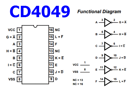
I checked all the voltages based on the chart below. Everything is good except for the 16-pin IC3 (CD4049UBE). On IC3, pins 5, 7, 9, 11, and 14 should read 0v. Instead, they all read ~9v. (The other pins are correct.)
IC3 - Pin 5 | Should read 0v | Reads ~9v
IC3 - Pin 7 | Should read 0v | Reads ~9v
IC3 - Pin 9 | Should read 0v | Reads ~9v
IC3 - Pin 11 | Should read 0v | Reads ~9v
IC3 - Pin 14 | Should read 0v | Reads ~9v
Here is a link to the build document:
Aion FX Maelstrom Documentation
I reflowed all the solder joints and checked every connection. It all looks okay. I'm unsure what to do next to address the IC3 readings above. Any help would be appreciated. Thank you!

Last edited:


