
jhalton
New member
Not sure if this is an okay forum for this, as its technically not DIY?
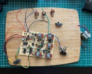
So, this pedal served me for many years, then stopped working (around 2004). I paid a guy to repair it, and long story short he made everything worse. I threw it in a box.
Fast forward 20 years, and I have been successfully building diy pedals for a year now. I figure I may have the skills to get this working again (possibly), but need help. I am not electronics knowledgeable (I just put components into PCB's!).
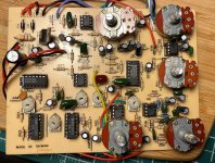
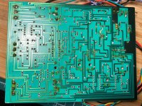
I am hoping someone out there has the time and will to give my some direction? I will add some photos below. I've already done some work, but I need to do off-board wiring now, especially the power section. The 24v doesn't seem recoverable to me, plus I'd like a more user-friendly power option if it all possible. Anyways, thoughts are welcome.
The main thing I'd like to do is the power mod like shown at this blog: https://sites.google.com/site/david...leeffects/electro-harmonix-memory-man/ec-2000
I also did a post at r/diypedals (https://www.reddit.com/r/diypedals/s/Ua2ef19laI), so I will copy what I wrote there:
To sum up, I need a new power option. The big transformer you see in the second picture is not recoverable. I want to change it to use a typical 2.5mm coax connector. I know this is possible, as I found a reference to it being done (David Morrin - EC 2000 Deluxe Memory Man Reissue). I will also probably swap the switch to a 3pdt (maybe).
So, i just need to know which wires on the PCB go to where, specifically the 4 on the top left of the PCB. The rest either go to the footswitch, the chorus/vib switch, and the jacks. From what I can see on the blog i referenced above, he removed one diode (D2), added another and another resistor. Not sure what is going on there.
I think I can figure out the rest of the wiring , but the power issue is out of my knowledge level. Hopefully this makes more sense, not sure how else to explain it!