First Build, getting no sound. Sandspur Fuzz

Verbzilla

New member
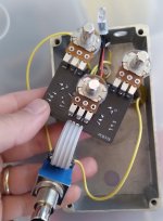
Does anyone see anything wrong from the photos? Pedal switches on with no sound. Bypass signal works fine and led comes on.

I think the transistor readings are way off. What would cause this?
Transistor readings with multimeter (volts)
Q1:
E 0, B.022, C.459

Q2:
E 0, B.459, C.442

Thanks for your help, I'm sure I must have screwed something up? Haha
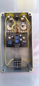
 

Attachments

  • 20260927_131152.jpg
    20260927_131152.jpg
    199.4 KB · Views: 77
  • 20260927_165927.jpg
    20260927_165927.jpg
    227.6 KB · Views: 77
When you say "The circuit input is not grounding out" what did you test?

I propose you use a DMM in continuity mode to check these 2 when the effect is supposed to be on and not bypassed:

1. the IN pin on the PCB and GND
2. the OUT pin on the PCB and GND

I think you already did (1) and confirmed it is not shorted when the effect is supposed to be on, but can you also do (2)?

One time I put too much solder on the footswitch pins and it grounded and shorted them on the other side of the PCB (the part sandwiched between the switch and the PCB). This took me awhile to diagnose and desoldering that footswitch PCB is a huge pain. To test this theory you could also remove the footswitch board entirely and test wiring the effect PCB IN to the input jack directly and the PCB OUT to the output jack directly, this completely removes the entire footswitch from the debugging. I no longer put as much solder on the footswitch pins.

You might be able to shine a light through the crack of the footswitch PCB in multiple orientations and see if there are any blobs/bridges that shouldn't be there.

I do this with aligator clips and a capacitor for my audio probe
Do you mind showing me an example of a foot switch daughterboard you have soldered up? Just trying to gauge what an acceptable amount of solder on the foot switch pin is for the future. Thank you!
 
Do you mind showing me an example of a foot switch daughterboard you have soldered up? Just trying to gauge what an acceptable amount of solder on the foot switch pin is for the future. Thank you!
It is totally subjective I think, and might not be a common problem, but since I ran into it, it is just something I am now cautious of. I put in an amount that seems to make the connection and stop, but more importantly I make sure it is actually melting where I want it to be. Sometimes with surface tension or whatever, this means the hole is perfectly filled, other-times not. I do the same for toggles as well.
 
It is totally subjective I think, and might not be a common problem, but since I ran into it, it is just something I am now cautious of. I put in an amount that seems to make the connection and stop, but more importantly I make sure it is actually melting where I want it to be. Sometimes with surface tension or whatever, this means the hole is perfectly filled, other-times not. I do the same for toggles as well.
Totally makes sense. I will be cautious of this as well moving forward. I was trying to make them all uniform as opposed to making a connection and then stopping. Good info to know, thanks again.
 
Do you mind showing me an example of a foot switch daughterboard you have soldered up?
build reports in the forums
edit- looking a this a little closer, check this area.. it looks like there's flux goop between your sw and gnd. electrons will try to go everywhere, they're like water in that way
 

Attachments

  • Screenshot 2026-10-06 at 14-47-00 First Build getting no sound. Sandspur Fuzz Page 3 PedalPCB ...png
    Screenshot 2026-10-06 at 14-47-00 First Build getting no sound. Sandspur Fuzz Page 3 PedalPCB ...png
    48.8 KB · Views: 3
Last edited:
I think there is such a thing as being TOO nice when helping new builders.

I’m not saying that we should return to the dark times when I started and you needed to earn every scrap of information from more experienced builders, but sending such a simple circuit to someone else to troubleshoot is a real missed opportunity.

Hopefully, you get something out of this, but I can’t see that happening in any real way.
 
I think a little bit of help is ok.. plus I'm totally going to point out his failures... :ROFLMAO:
Let's just call this one a get out of jail free card..... next time he's gonna have to gruel through it and test all the spots we tell him to. Besides..... soon enough one of mine will be in this section as well and I'll be stumped. I'm still no wizard... Yet.
 
I'm very grateful for everyone on here that has chimed in. I've never soldered, used a multimeter or messed with electronics before. I have learned so much already. It will be very helpful to have someone go over everything and let me know what I need to change.
 
Back
Top