Flock Harmonizing Fuzz - getting feedback squeal

mcluff

Member
Maddening problem with my Flock Harmonizing Fuzz. Thanks to this thread, I've tried re-flowing the rotary switch pins (and pretty much everything else), swapped out ICs and such. Still, no joy!

The problems:
  1. Persistent feedback squeal where the pitch changes based on the "track" knob.
  2. Nothing changes with the rotary switch
Squeal detail: doesn't go away if you stop sending audio through it.

Here's my quickie video of the problem:

IMG-6599.jpg IMG-6600.jpg
 
My flock did the exact same thing. I ended up swapping out 46 and 24 and reflowing. I think ultimately I had a bad 46 (I may have overheated it in reflows) combined with flow issues on the rotary child board. If you have header pins from Tayda they are hard to get the solder to stick to them in some cases and it’s next to impossible to see what’s going on under that board sandwich.
It sounds like you did all the same trouble shooting. Have you checked all the joints with a magnifier maybe something is not connecting. You could also trace the sound and see where the oscillation starts up. Good luck I know how frustrating this one can be. But it’s worth all the effort once you remedy it.
 
Maddening problem with my Flock Harmonizing Fuzz. Thanks to this thread, I've tried re-flowing the rotary switch pins (and pretty much everything else), swapped out ICs and such. Still, no joy!

The problems:
  1. Persistent feedback squeal where the pitch changes based on the "track" knob.
  2. Nothing changes with the rotary switch
Squeal detail: doesn't go away if you stop sending audio through it.

Here's my quickie video of the problem:

View attachment 40737View attachment 40738
Resurrecting a zombie thread, I'm having the same feedback issue with my flock. Did you ever get this one sorted?
 
Is it me or is C1 backwards on that schematic?
Also, I have a really loud whine on pin 1 of my TL72, and an intermittent burst of noise every few seconds. Can someone post working voltages for the ICs please?
 
Last edited:
Is it me or is C1 backwards on that schematic?
...
No, not backwards.

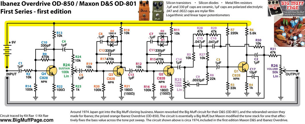
Have a look at the input cap. here:

and at the following — notice that all the polarised caps have their + side facing towards the nearest transistor
(C1 C4 C5 C13 C14 C3 C17 C2):

Ibanez_OD850_FirstEd_Schematic.jpg


Sorry I can't help with your other question.


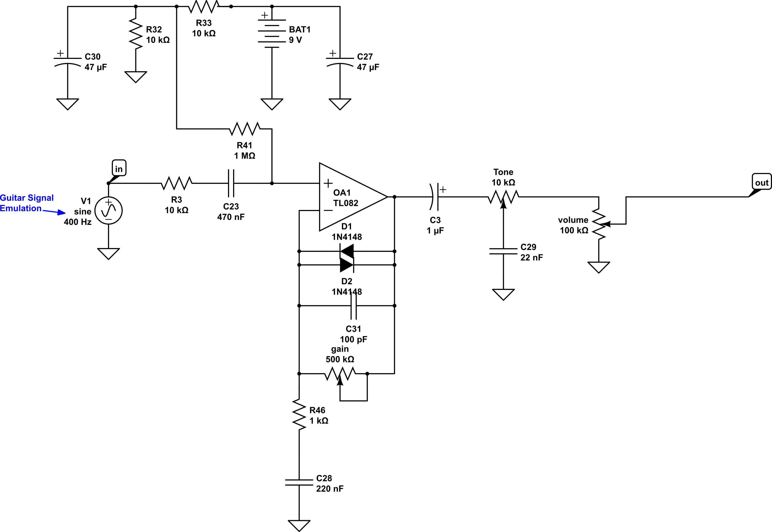
EDIT: Here's a Wampler schematic where it points away 🤷‍♂️...

tone-control1.png
 
Last edited:
Back
Top