Fumble boost 1590b

AceHyzer

Well-known member
Build Rating
5.00 star(s)
When JHS dropped the notadumble I picked one up. I didn't care much for the zendrive circuit, but I did really like the boost. It has been on my board since I got it, but taking up way too much space for a simple clean boost, so I was stoked to be able to get it into a smaller 1590b enclosure to save a bunch of space!

Since we found out after the fact that it's actually the BBC-1, I used the labels that dumble actually used on his BBC-1 circuit, Gain, and Depth. I especially think "Depth" describes what that knob does sonically, really well.

IMG_3403.jpeg

It was a quick and straightforward build, though I did fry a J309 and didn't do much better with my second try. Must've been tired or something because I've done a lot of SMD soldering and have never fried one before. I was worried it wouldn't fire up but it did fire up just fine!
IMG_3402.jpeg

It's a huge space saver on the ol' pedalboard. I've included a pic of it on my board with the notadumble above it so you can see just how much space I'm saving! Also, a leak of a handful of builds that I've never done build reports on because I'm bad at doing them, even though I should!

IMG_3404.jpeg

Anyways, it sounds great. I did a side-by-side comparison and there was a very slight difference in tolerances of the depth pot, but with my depth pot turned down just a hair further than the original I was able to get it to sound identical. Very stoked to free up some space on the board!
 
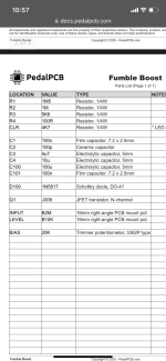
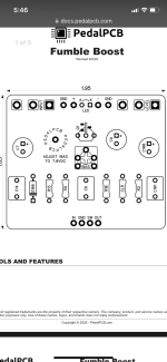
Hey man! I saw your post of the Fumble you did. It looks amazing. I just purchased 2 of these pcb’s and want to make one for myself and 1 for my brother. We both have the NotaDumble but really want just the clean channel in a smaller pedal. However, this will be my first pedal build. Is there any way on earth you could send me a list of the components you purchased? I know that’s a huge pain but I was trying to follow their parts list and there just doesn’t seem like enough info for me to follow. Again. I know you probably don’t want to spend the time but I feel like looking at their parts list and the schematic of the board the locations aren’t all there either. Did you find the same?

Any help would really be appreciated.

Keith
 
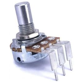
Keith, just go on tayda.com, all the parts you're going to need are 1/4 watt metal resistors, box film capacitors, and electrolytic capacitors. Soldering the SMD transistor is definitely not a noob leveI thing though. I don't want to discourage you, but it is very tiny and easy to mess up if you are not familiar with how to make solder flow exactly the way you want. If you can find the transistors pre soldered into a thru leg format somewhere, I would go that route. Read the items carefully to make sure you're getting the right kind, ie PCB mount 6.35mm potentiometers.
 
Keith, just go on tayda.com, all the parts you're going to need are 1/4 watt metal resistors, box film capacitors, and electrolytic capacitors. Soldering the SMD transistor is definitely not a noob leveI thing though. I don't want to discourage you, but it is very tiny and easy to mess up if you are not familiar with how to make solder flow exactly the way you want. If you can find the transistors pre soldered into a thru leg format somewhere, I would go that route. Read the items carefully to make sure you're getting the right kind, ie PCB mount 6.35mm potentiometers.
Hey man. This is great info. I actually do quite a bit of soldering for many different applications but I guess not this small now that I think if it. Im just not sure that I am ordering exactly the right caps and resistors based on what this chart is telling me also the numbers on the list don’t exactly match the locations I see on the board diagram. I will attach pics.
 
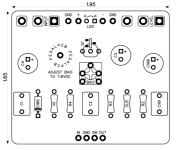
See how there is a c14 on the diagram but no c14 on the list? Sorry for so much info. Just a bit confusing.
I'm not at home right now so I don't have the board on hand to verify, but I'm pretty sure C14 on the diagram is actually C1, C6 is C2. I'm pretty sure if you order everything on the BOM you'll have what you need. So, two 100n film caps, one 100p ceramic, and all 3 electrolytics listed.

As mentioned above, Tayda will have pretty much everything you need if you search for it. This circuit runs on a standard 9v so any electrolytics that are rated >= 16v will do the trick. I usually just order electrolytics in bulk that are rated at 50v because that covers all my pedal needs outside of a few special cases with tube-based circuits.

I'd recommend dropping the cash on the through-hole J309 that @Robert posted above if you haven't done any SMD soldering before. Especially if this is your first build.

I agree with pretty much everything @falco_femoralis posted as well. I personally prefer C0G or NP0 ceramic caps, WIMA film caps, and panasonic/rubicon/Nichicon electrolytics. Realistically though, any ceramics, electrolytics, and film caps you find on Tayda will do the trick unless you partake in minor to moderate levels of cork sniffery.
 
Thank you Ace! No cork sniffery here lol. This is huge help! All of you are awesome. Much much appreciated. I may bug you again if I can’t find the right spots but I hope I’ve got it thank you!
 
Here are some pics of one I did, you can see the component values

bjQEw4A.jpeg


6teNkxU.jpeg


PMGRjdM.jpeg


Don't forget the B2M pot
 
Y'all are the best! Feeling wayyyy more confident now. Great advice and thank you for fixing the Diagram! I will post back here once I get everything all done.
 
Hey man. This is great info. I actually do quite a bit of soldering for many different applications but I guess not this small now that I think if it. Im just not sure that I am ordering exactly the right caps and resistors based on what this chart is telling me also the numbers on the list don’t exactly match the locations I see on the board diagram. I will attach pics.
You really need a good adjustable iron with a small tip.. some rosin type flux . and a magnifying lamp to do smd efficiently without worry.. I'd slap it on for you if you are stateside.. you can send me the pcb and smd's and i can mail it back out for you.. I picked up one of these boards too. and havent ordered the transistor yet.. I have stock of all the other goodies.. just didnt have any of those trannies..
 
@KeithB it isn't that hard, just super fiddly. They are really small. I use a 2mm tip, same as normal. I tin the solder pads first with just a small amount, then use needlenose and place the smd component over the solder pads. Apply some heat and downward pressure to one pad with the needlenose or a small screwdriver (whatever you're most comfortable with) and it will soak in. If it gets misaligned then I go back in with a small flathead and nudge it over. It's important to go in short, small, decisive movements to keep the heat soak to a minimum, and get it lined up first before continuing to the other pads. When it's straight I'll do the other two pads, they usually don't have a problem. Just apply some quick heat and downward pressure with a screwdriver and it'll soak in. Just remember, you can use a good amount of heat, like 750F, but only apply it for a second. If it gets weird take a break and regroup
 
Same… I apply a small dab of rosin.. then lightly tin the pad with tip of my iron.. rosin again.. line up the SMD component and it stays in place with the rosin paste… tin my tip and heat the part.. there is enough solder on the tip to flow over the component and lock it down… Hot and fast!
 
LUCKILY there is an alternative to the J309.


According to KR-Sound's compatibility doc...


... the NTE2902 can be used as a replacement for the J309.

They're only $23 on Amazon, each!


Elsewhere, though, you might find them for just under $5.
 
Back
Top