BuddytheReow
Moderator
The Fuzz Face. One of the first and most iconic fuzz circuits around. It is debatable whether there are more iterations of this classic circuit or the Big Muff Pi out there, so I'll let you be the judge. For any breadboarder or pedal creator out there, the Fuzz Face is almost a rite of passage in your build journey. IMO, everyone needs to build or play through a Fuzz Face, a Rat, and a Muff at some point in their life. They all have distinct sounds and are useful in a multitude of situations.
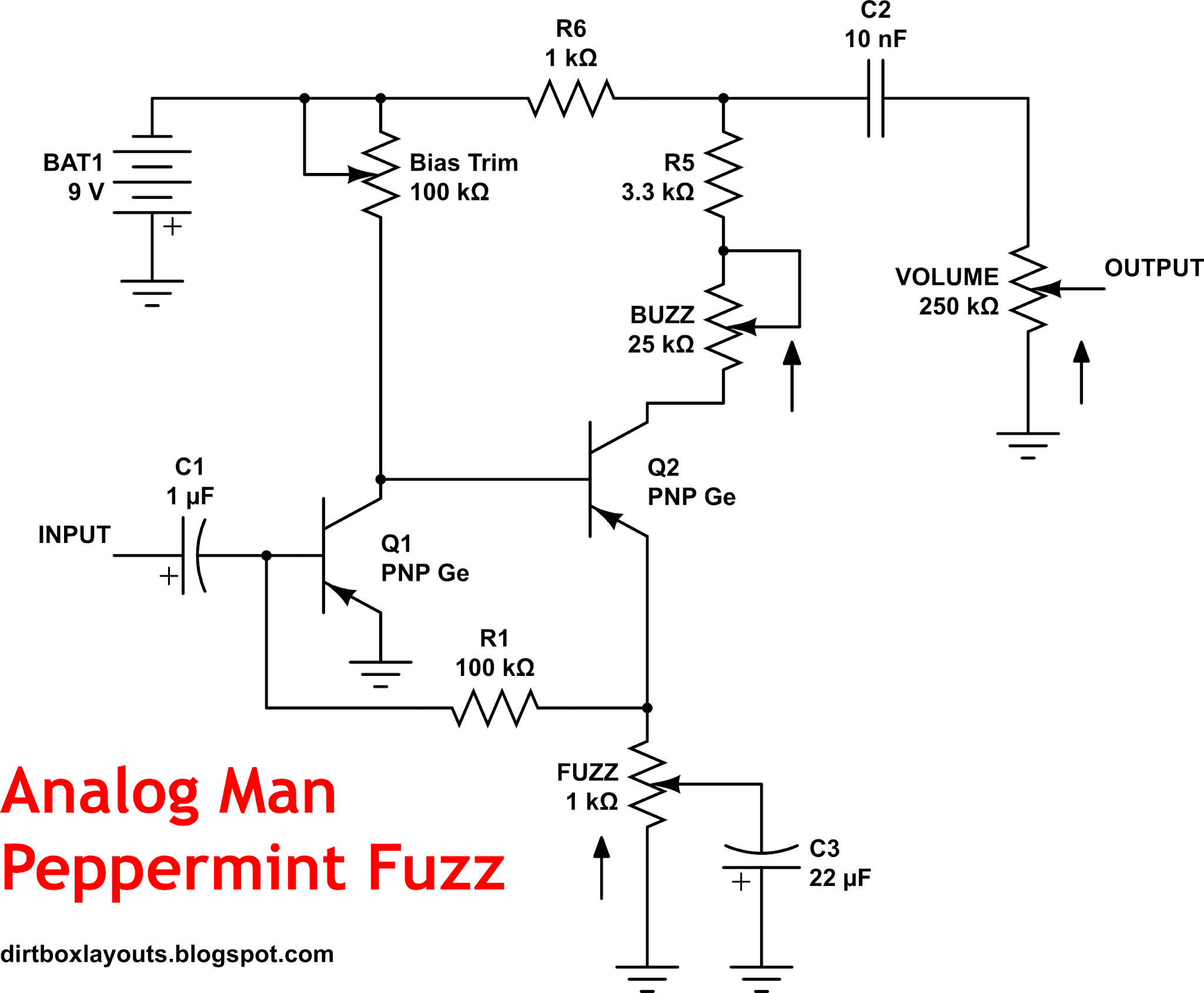
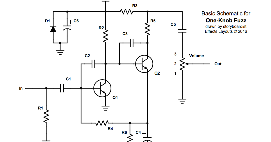
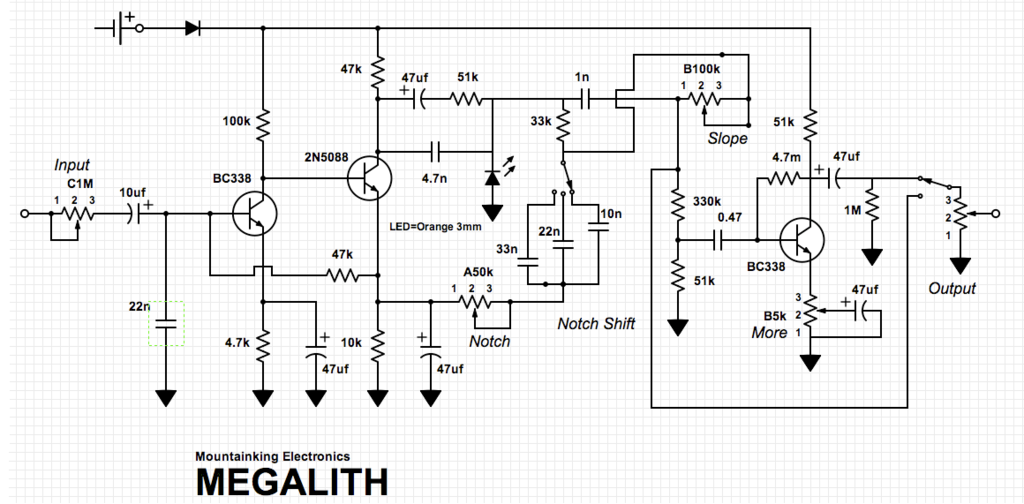
My request from all of you: if any of you have found a great fuzz face derivative please share it in the comments below. I just ask that you also include a schematic as well for future builders/breadboarders.
A few words about the Fuzz Face. Like I said, this is almost a rite of passage to build. If you'd like to learn more about how the circuit works there are a ton of resources out there, but here are a few that I've found.
 forum.pedalpcb.com
 www.electrosmash.com

 barbarach.com
It should also be noted that the original circuit used PNP germanium transistors simply because that's all that really existed at the time. NPNs were expensive and from my understanding, unreliable. The topology I have below is wired for modern day silicon NPN BJTs. In theory, you can switch out NPN for PNP and apply -9V in the power section, but you may need to adjust some part values a bit. PNP germanium transistors are a bit harder to find (and a bit more expensive) compared to NPN silicon.
The original fuzz face had two knobs: FUZZ and VOLUME. Most people just crank the fuzz control and leave it there since it sounds best IMO. These one knob fuzzes just remove the pot and swap it for a resistor (usually 1k).
Since there are so many derivatives out there, I'd rather share how to breadboard just the overall topology. For my layout I decided to try out the DAM Meathead (Dark). Here's a schematic I created. C2 and C6 are not in every FF version, but in my layout they are.

For the DAM Meathead Dark, here is the BOM based on my ref des:
C1 470n
C2 470p
C3 100n
C4 100u
C5 10u
C6 47p
R1 1k
R2 18k
R3 120k
R4 820 ohm
R5 4.7k
Q1 BC108
Q2 BC108
VOLUME A100k
And the final build. Ready to get started?

My request from all of you: if any of you have found a great fuzz face derivative please share it in the comments below. I just ask that you also include a schematic as well for future builders/breadboarders.
A few words about the Fuzz Face. Like I said, this is almost a rite of passage to build. If you'd like to learn more about how the circuit works there are a ton of resources out there, but here are a few that I've found.
Biasing BJTs - part 3
This time we'll focus on the Fuzz Face. The Fuzz Face has a long and colorful history that is beyond the scope of this discussion. The original FFs were built with PNP Germanium transistors because that's what the pedal builders had to work with. In this discussion, I'll talk about NPN...
ElectroSmash - Fuzz Face Analysis
The Fuzz Face is a distortion guitar pedal designed in London by Arbitrer Electronics Ltd in the autumn of 1966. This analysis covers the first Arbitrer Fuzz Face model equipped with PNP germanium transistors from the first releases.
Building a Fuzz Face Clone - Intro & Analysis - Barbarach BC
I'm building a Fuzz Face clone - a famous pedal used by Hendrix, Gilmour and many others. The first post: intro and analysis.
barbarach.com
It should also be noted that the original circuit used PNP germanium transistors simply because that's all that really existed at the time. NPNs were expensive and from my understanding, unreliable. The topology I have below is wired for modern day silicon NPN BJTs. In theory, you can switch out NPN for PNP and apply -9V in the power section, but you may need to adjust some part values a bit. PNP germanium transistors are a bit harder to find (and a bit more expensive) compared to NPN silicon.
The original fuzz face had two knobs: FUZZ and VOLUME. Most people just crank the fuzz control and leave it there since it sounds best IMO. These one knob fuzzes just remove the pot and swap it for a resistor (usually 1k).
Since there are so many derivatives out there, I'd rather share how to breadboard just the overall topology. For my layout I decided to try out the DAM Meathead (Dark). Here's a schematic I created. C2 and C6 are not in every FF version, but in my layout they are.

For the DAM Meathead Dark, here is the BOM based on my ref des:
C1 470n
C2 470p
C3 100n
C4 100u
C5 10u
C6 47p
R1 1k
R2 18k
R3 120k
R4 820 ohm
R5 4.7k
Q1 BC108
Q2 BC108
VOLUME A100k
And the final build. Ready to get started?

Last edited:


 Sometimes I forget what is already known! Excellent, MDC!