mjh36
Well-known member
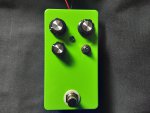
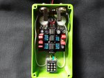
Finally got it respectably put together. It's my second build, eventually I'll get a better case, as this did NOT turn out the easiest. The bottom of the switch lugs contact the pcb, tried electrical tape (which you can see on the left) but it still makes the gain knob not work. So the nuts for the potentiometers are loose to lower the pcb board so there's no contact.
But works great. Tons of volume on tap, more than enough, especially in the middle switch position. I gotta step my artwork game up though, you guys make some good looking pedals for inspiration.
BTW what's the switching on this? I think it's Left LED, Middle "normal" (IC's?), Right silicon diode?


But works great. Tons of volume on tap, more than enough, especially in the middle switch position. I gotta step my artwork game up though, you guys make some good looking pedals for inspiration.
BTW what's the switching on this? I think it's Left LED, Middle "normal" (IC's?), Right silicon diode?


