...continued from before
I ended up adding some standoffs to raise up the lid. It works, but it's messy and I'll probably redo my enclosure at some point.
Pay attention to how the knobs connect to the circuit
I didn't think it through and I originally put the knobs on wrong. In my original mounting I had terminals 1 and 3 on the potentiometer swapped. Everything worked, but the operation was counterintuitive. I already cut holes for the knobs so I ended up cutting off the pot leads and fixing it with jumper wires.
Consider other JFETs
I used MMBF5457 (surface mount). Surfybear lists MMBF5457 as an alternate for their kit. I checked the signals with a scope and everything looks good.
Pick the right kind of cable to connect to the tank
A lot of cheap audio-visual RCA cables share a ground between the channels. This causes the drive signal to interfere with the received signal.
Other Random stuff
I added a 2.2 Meg resistor to ground at the output. It's not really necessary, but it'll keep the output from floating.
As others mentioned, the LED resistor could be a higher value.
I intentionally used an odd connector for power. I don't want to accidentally connect this to the wrong supply.
That's all I can think of. The thing sounds awesome, but it's easily the most challenging pedal I've ever built. Good luck.
Hello! I am a complete beginner at soldering. I've fixed up the wiring in 2 guitars, made a simon says practice soldering kit, and I am almost done with my Moody Sounds BJF Universal Reverb. I finished the pcb, and I've been working on the enclosure design before I actually start connecting the pots and stuff.
After attempting to read through a couple of threads including this one, a lot of the stuff you guys are saying go right over my head, and it seems like this will be an extremely challenging build. I can look at a parts list and figure out what goes where, but I have no idea why it goes there. I don't know what components do, and I don't have or know how to use a multimeter. I've already ordered the ricochet, and when you scroll down on the griffon effects page for the ricochet, there is a link to the parts list and improved mixer parts being sold on Mouser. I just added all of that stuff to my cart and it'll be arriving as soon as the back ordered parts are in stock.
That being said, since the ricochet doesn't come with components, and I see you guys mentioning swapping out one of the resistors and needing heat sinks and such, I have no clue what I need to buy to make this work. Could you send me links for the rest of the parts that I will need? Enclosure, heat sinks, R15 replacement, etc?
I also have the Anasounds Element and the Bulinski ASD-1. The anasounds element stinks! Even though it connects to a spring tank, even with me using the SurfyBear pan extra, it doesn't sound like a spring reverb at all! I contacted them asking about that, and they said that it is more like a hall reverb. The Bulinski is much better, still not drippy enough, but it's better than the anasounds. When I contacted Bulinski about it, he mentioned he is planning on making a FET Spring Driver in a smaller enclosure, more like the fender 6G15, he just hasn't gotten around to designing the circuit board yet.
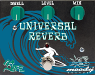
Here is the design I came up with for the moody sounds kit
")


 )... so I'm guessing you are probably not sticking your build in an amp. No-can-give a shopping-list or links for the rest of what you need, you'll have to figure that out, people here will help however they can if you have more specific queries.
 ).
).