Griffin Ricochet (Surfy Bear Clone) Issues

Brandalones

New member
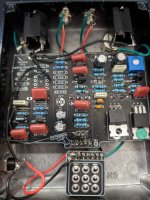
I just finished a build of the Griffin Effects Ricochet (https://griffineffects.com/byo-pcbs/modulation/ricochet-pcb) using the original mixer, and am getting power and signal in both bypassed and on positions, but when on, I don't get any reverb, only like a fuzz when dialed wet. No crash sound if I shake the springs either. I had the TP1 getting voltage at about 6.6 after adjusting R13. I also read on another post that someone tried removing Q3 - BC557B so I also did that. No real change.

Any ideas what else could be the issue? My only thought is maybe one of the MOSFETS are fried, but I am getting voltage readings on both of them. I don't know what they should be reading at each pin though.

View attachment 72244
 

Attachments

  • 1712190382743.gif
    1712190382743.gif
    42 bytes · Views: 11
let's start with low hanging fruit ...
what's your power supply rated for in both volts and amps?
is your reverb tank connected properly and properly spec'd for the circuit?
did you do anything silly like leave the packing material in the spring tank?
did you properly spec the jfets and if so, how?
do you have pictures of anything?
do you have an audio probe?
did you make any parts substitutions?
 
I'll go through each question...

what's your power supply rated for in both volts and amps? 12v 1000mA

is your reverb tank connected properly and properly spec'd for the circuit?
Connected properly, yes. I tried one I had bought, but it's 10ohm input and 2750 ohm output, so a little off. I also tried one I pulled from my Super Reverb, though I don't know the specs. Same results.

did you do anything silly like leave the packing material in the spring tank? No, I made sure to remove that right away.

did you properly spec the jfets and if so, how? No, not sure about how to do this.

do you have pictures of anything? I'll add some.

do you have an audio probe? Yes, but it's not great, and I'm struggling to understand some of the readings. I did check that I was getting 6.6v at TP1, and I am seeing voltages at the jfets, but not sure what they need to be.

did you make any parts substitutions? Initially, no. While troubleshooting I have swapped R13 for a few different values, trying to get TP1 down to 6v. I have also removed Q3 (BC557P) which seemed to increase the signal a bit, and now giving me about 7.3v at TP1, but no significant change to the reverb issue.
I do see on the schematic it says C13 is not in the original, but there were no instructions to not include it. It's just part of the tone stack anyway.


The board is starting to look a little messy from removing parts and fixing solder joints, but the problem has been there from the beginning.
One jfet is lifted a bit because I had soldered it before bending, and realized I didn't leave enough on the leads to get it to line up with the little hole.

Thanks for the reply!
 

Attachments

  • PSX_20240404_134045.jpg
    PSX_20240404_134045.jpg
    437.2 KB · Views: 19
I'm going to start this off in a "familiar for these parts" sort of way and tell you that this is not a novice project and you are a novice builder. It's not a cheap project either, as you are finding out.

Any time a project has specifications for their parts, you should be paying attention to them because they are important. We can wrap this troubleshooting session up right here because we can inspect all the joints and take all the voltage measurements your multimeter will gather but until you have known good working transistors of the proper specs, we'll be playing with ourselves and hoping at some point to finish. Put some sockets down, replace your jfets with the right ones of proper spec, put a new PNP back (in a socket too) of the proper spec, and plan on addressing the heat the MOSFETs put out because they do get hot when they're doing the job properly.

We can pick this back up when you've done that and are still having issues. I imagine when you work through all that you'll resolve the problem without further need of my help.
 
Copy that. I did order the "correct" transistors required by the build, but must have gone too cheap or something. The only spec mentioned in the build instructions is: 2N5457 selected for: Vp: -1.58V ldss: 3.27mA
I do have some spares, and ordered another set of mosfets in case I fried these. Also ordering some sockets for all. Is there a manufacturer you'd recommend for the transistors? the BC557P was Vishay but the rest were where I think I went cheap.

I'll see if I can get the Mouser parts list from Griffin to work, it wouldn't load anything for me, so I was purchasing somewhat blind.

Thanks for the advice. I'll report back after running through everything.
Just so we're clear, brand has less to do with it than hitting those specifications. So we're not back here an hour after you open your parts order bluffing me that you got the right parts this time, that means you have to have a way of measuring those parts to verify they meet those specifications. You don't know how to do that so you should probably skip spending any more money until you do then you can tool up (if necessary) then you can buy the parts (if necessary) then you can fix your project
 
Are you suggesting I'm lying or ignorant about which parts I ordered? I got the parts required for the build. Now, if they're defective or somehow out of spec or out of tolerance, that could be an issue. But they aren't some random transistors I just threw on the build.
I have a tester on order as well, to see if the parts are in spec.
I do appreciate the help, but you should really work on your tact.

Anyway, I'll post my findings after I get what I need.
 
@ICTRock may be being a bit blunt, but he’s telling you important things that you seem to be missing.

Part number is less important than the specs of the individual transistor. Transistors vary, sometimes widely, even within the same part number and batch. The transistor tester you ordered, if it’s one of those cheap Chinese testers, won’t give you the readings you need for a Jfet. Look up the Run Off Groove method for the fetzer valve transistor testing.

Lastly, be patient and try to soak up knowledge from the wealth of information on this forum. Lots of smart people here.
 
Are you suggesting I'm lying or ignorant about which parts I ordered? I got the parts required for the build. Now, if they're defective or somehow out of spec or out of tolerance, that could be an issue. But they aren't some random transistors I just threw on the build.
I have a tester on order as well, to see if the parts are in spec.
I do appreciate the help, but you should really work on your tact.

Anyway, I'll post my findings after I get what I need.
It's all good, when you get your parts in I'll be too busy working on my tact to help you any further.
 
I joined your forum because I'm building a Ricochet reverb and ran into the same problems as the others. After a few days of research and unsuccessfully trying to get the reverb to work, I dug into the schematic and I think I found the problem. R15 determines the BIAS current through the MOSFET output stage. To me, it seems quite large compared to other amplifier schemes that drive the 8 Ohm impedance of the Reverb tank transmitter coil. Further research has shown that a 1.5 Ohm resistor is used in the MOSFET pair IRF501 and IRF9501 on the 12V supply, which with the help of PNP BC557 sets the BIAS current to about 400mA. In the schematic for the Ricochet reverb, this resistor is incorrectly labeled as 1K5. Such a resistor sets a thousand times lower BIAS current, i.e. 0.4mA, which is practically ZERO. Such an output stage cannot drive the 8 ohm impedance of the Reverb tank transmitter coil. So everyone who Ricochet doesn't work for you, replace the resistor R15 1500 Ohm > 1.5 ohm (0,5W) and add bigger heatsinks to both transistors. I hope I helped someone to get a working reverb.
 
I wouldn't go that far ... I'll look at this again later tonight and provide a breakdown of differences, whether they're important, etc.

I actually bought another PCB because I wrote nothing down when I built the first one and it is gone and out of my ability to reference.

I did have my suspicions about the work of others because nobody else has mentioned the hot transistors and they do get hot when everything is working as it should. Also the way I do things isn't the way others do things (reference multiple schema, not paint by numbers, etc.) so just because I was successful doesn't mean you were going to be successful or that I would be successful again.

I do still stand by previous statements that even if you get the rest of it right, the jfets not being within spec will fuck this build just as fast as the MOSFETS receiving no current. through-hole jfets aren't nearly reliable enough to just plug in and expect to play, even if they get biased to the expected voltage (how you end up biasing by voltage first then by ear)
 
Last edited:
So I went through the schema and here's my notes of what's different. Part numbers belong to the Ricochet.

R25 - 1K is pretty low for a LED resistor on a 12V 1A supply
TR1 - The surfy bear didn't have this and that just means you set the trimmer for 0R if that's what you want.
R15 - The surfy bear value is correct at 1R5. The transistor is there to drive current.

That's it with the exception of the improved mixer option. Those values are a direct pull from the surfy bear thread over at FSB.

Coming here and correcting R15 is good. Coming here and saying the whole thing is wrong is not good.
 
Last edited:
I'd sincerely doubt Bill at Griffin would release an unverified board

I know nobody's dissing him but he's a very helpful guy in my experience

I'm sure if the schematic was completely wrong folks in forum land would let us know and Bill would be on it

I don't know how many successful builds are out there but it's a popular pcb and I've seen a few

If the BOM tells you to get whatever that's what I'd do, so I agree with @ICTRock if you haven't used what's specified that may be the problem

Just for info I tested 25 x 2N5457s on my DCA75 not one was close to the specs albeit they were within datasheet parameters so you'd need to test a few unless I'm Unlucky Luciano
 
Back
Top