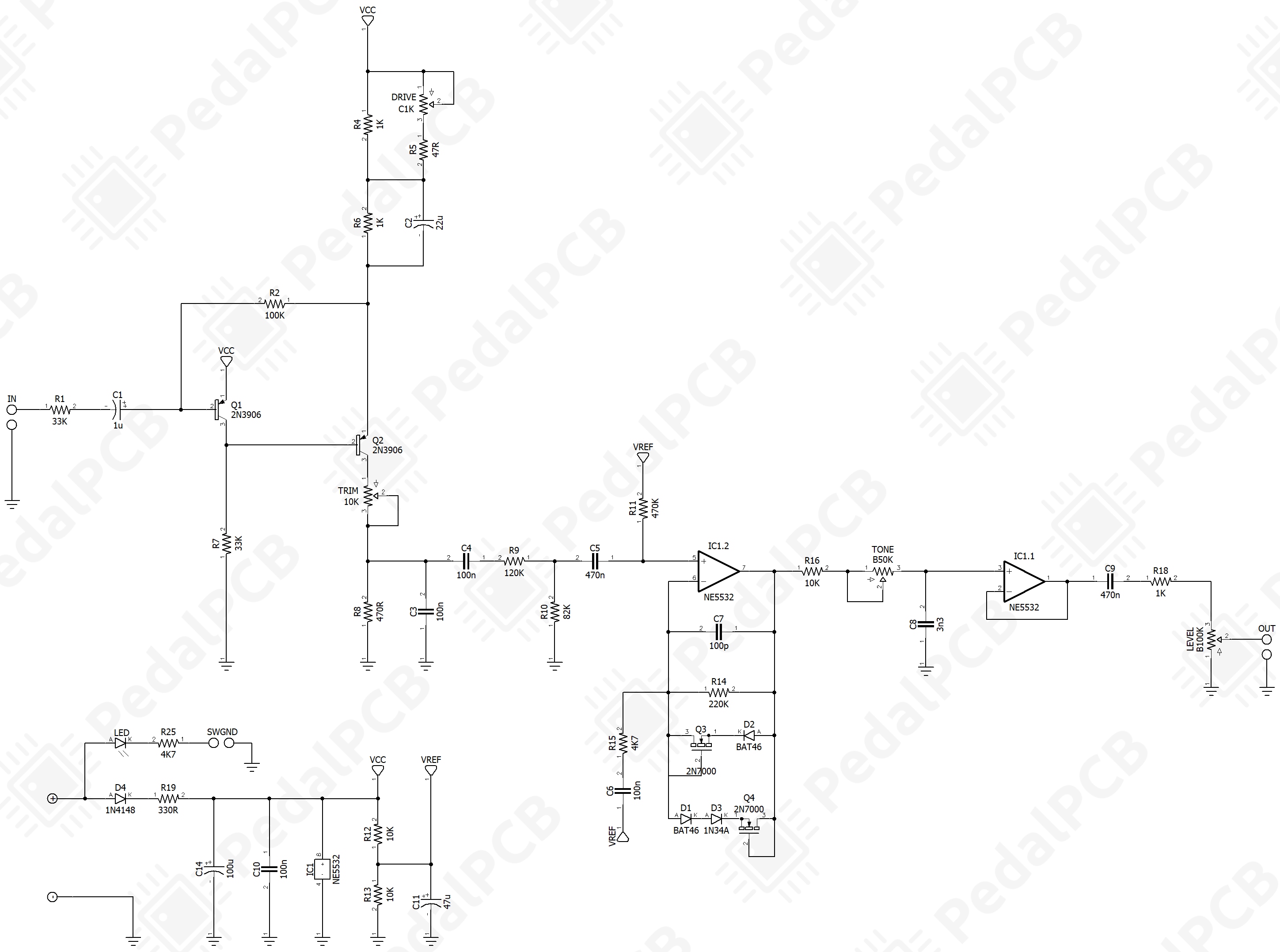
Grover drive question.

When there is a Build Doc with a schematic, then we can talk intelligently about the 5lb Bag circuit design.

Tell us more about this 100nF cap that's allegedly amiss in the Grover. I can't find it.
 
Very clean build. Wire routing is impeccable.

Three questions:
1. How is the board supported?
2. Are those transistor bodies touching?
3. You changed Q1 & Q2 from Si to Ge. This will alter the biasing. How to you plan to deal with that?
the pcb is attached to the Fuzz pot and the volume of the Zen drive + about a dozen other spots with my jumpers bent at right angles. for the transistors i was planning on getting some clear heat shrink tube and put it around the body of each transistor to keep them from touching. using germanium transistors forced me to adjust the Q1 biasing resistor R2 i had to drop it down 15k for my Q1 to hit around .7-.8v i didnt have to change anything for Q2 i was able to hit 4.5-5v with the trimmer , Q1Hfe is 84 Q2 Hfe is 140. i have played a bit on it and it sounds really nice but i need to go over the clipping section on the Zen Drive once more its not sounding like it did on my breadboard, i think i put my Bat 46 in the place i wanted a Bat 41 also im wanting to adjust a couple other values i thought i was happy with on the breadboard but not so much now .
 
If someone knows what C4, R8, R9, R18 & R19 are supposed to do, then please explain it to me.
C4 is kinda odd, ive seen a few schematics show C4 going to ground as a low-pass filter not as is a high pass filter as PedalPCB has it . that change seemed to make the circuit more stable on my breadboard . but because i wanted to sepperate the two circuits i needed to keep C4 as a decoupling cap/highpass then added that 100nf low pass in parallel with R4 on the bottom of the pcb .i wanted to blend from FF tone to range master tone so i changed the C2 100nf input cap to a 4.7 and use the blend pot i added to go between the FF/range master tones the R8R18/R9R19 is just a voltage divider. i think of it as a fixed volume pot. its to make the output of the fuzz match the input of the the Zen better so it doesnt go crazy and make a bunch of noise.
 
I know they are a voltage divider, but it's unnecessary because you can get the same effect by lowering R4. Or just jumper R18 & C5, delete R9 & R19, reduce R10 to 82K and you have the exact same transfer function with fewer parts.

Since you are splitting the Grover in half, now I see why you're doing what you're doing. Consider making Q1 Si, it will make the bias much more stable. Q2 dominates the tone because that's where the distortion is made. Use a medium-low HFE transistor for Q1 or increase R3 to dial-in the bias.

I like the idea of 100nF in parallel with R4, it rolls-off the higher harmonics above 3.4KHz. If that's too dark, then try 47nF.

Because of the feedback thru R3, a FF behaves differently than a Rangemaster. Varying the GAIN will change the high-pass freq because the gain of Q1 & Q2 makes R3 proportionately smaller from an AC point of view.
 
Maybe he's referring to the big blue cap bottom right which should be 100nF but appears to be bigger?
that big blue cap sounded so good on my Breadboard i swear LOL , when i put the fuzz into range master mode it kept a bit more low end . now it seems its way way to much low end so im going to slim that 1u down to the recommended 100nf .
 
When there is a Build Doc with a schematic, then we can talk intelligently about the 5lb Bag circuit design.

Schematic-5lbBag.png
 
I think maybe @music6000 was referring to C3, which isn't on the Grover / Dover Drive schematics.

I can't comment on that, since the Grover was based on the Dover Drive schematic that has been passed around for years.

The 5lb Bag, however, is based on my personal trace of the 200lbs of Gold.
 
that big blue cap sounded so good on my Breadboard i swear LOL , when i put the fuzz into range master mode it kept a bit more low end . now it seems its way way to much low end so im going to slim that 1u down to the recommended 100nf .
C4 & R9 make a corner freq at 13Hz. If you can hear the difference between that and 1.3Hz, then your hearing is better than mine.

...the Grover was based on the Dover Drive schematic that has been passed around for years.
In that case I don't trust the Dover Drive schematic.

The 5lb Bag, however, is based on my personal trace of the 200lbs of Gold.
THAT schematic I trust.
 
i think the old Schematic on line that is drawn out with blue ink pen on graph paper was changed , the guy that wrote it up later came back and said he made a mistake when he traced it the first time that one cap C4 went to ground other than that it was exactly the same .its an easy fix tho.
 
Once one error is found, the schematic loses credibility. The schematics passed around on the various forums have little or no traceability back to the guy that traced it and the unit he traced it from. Having traced dozens, if not hundreds, of boards over the years myself, I know how easy it is to get it wrong. Manufacturers will update designs and not tell anyone, so the unit that was traced and the one we hear on youtube may not be the same design.
 
The Boost circuit is just a simple opamp boost that comes after the fuzz.

View attachment 31606
this whole time i thought it was an electra type in the front end. i almost tried to add an electra boost to the front of my Dover with a third foot switch , lol im glad i didnt do that. thats way different from what i was thinking. ill have to breadboard this to hear how it sounds in the DD. TY for the schematic , im surprised at how close the Dover drive is to the 200lbs of gold.
 
Back
Top