Gunvernator Issue

Route14

Well-known member
I have two recent builds I’m having issues with.

Sliver works great except the Tone pot has no effect on the sound. I tested the pot with a DMM and it checks out.

Guvernator passes sound in bypass but no sound when engaged. However LED works When engaged.

Anything obvious I should check? I’m using breakout boards on both builds.

Thanks!
 
Try reading the other posts on this forum for tips on how to proceed.

It's customary for you to perform a thorough visual inspection under magnification to confirm that all solder joints are good, all parts are correct and facing the right way, and all off-board wiring is correct. 90% of the problems people post here are are solved using that method.

You need to post legible hi-res photos. We need to be able to read the ICs, resistors, caps, etc., see the off-board wiring and take a look at the quality of your soldering. This does not relieve you from the responsibility of doing your own inspection, but we might spot something you missed.

Tell us about anything you did that deviates from the Build Docs. Mods, parts subs, you name it.

Do all that and we'll jump in.
 
Will do. I’ve already double checked all the values against the build doc and I always check the joints under a magnifying glass before wiring up. No mods. Just wanted to see if there is anything I should check before removing the pots. I’ll follow the above and get back with some pics. Thanks again.
 
We're troubleshooting two different boards so it will be less confusing if you start two separate threads.

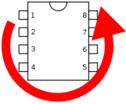
On the Governator, check the DC voltages on all 8 pins of the IC. Set GAIN to max. You might get some screwy readings on pins 3 & 6, depending on the input impedance of your DVM. 1-3 and 5-7 should all be near +4.5V.
 
Pins 1, 2 and 6 gave me good readings. 3 gave me 0.0 and 5 gave me .31. Since I've never done this before I just want to make sure I was doing it correctly. I set the DMM to V (DC) Black to COM and Red to V and with the power supply connected I put the black probe on pin 8 and the red probe on each pin to test. I also maxed the Gain knob as requested.

Thanks.

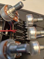
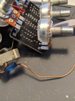
PXL_20201018_180250529.jpg PXL_20201018_180302378.jpg
 
What he said. Or you can ground the meter to one of the ground pins on the jacks.

Show us the other side of the board also. Some of the solder joints on the pots look cold, but it's hard to tell for sure.
 
Okay now I get .15-.17 on 1, 2, 6 and 7 and .27 on 3 and .6 on pin 5. I did the same process on a Shredmaster I built at the same time and I get the appropriate 4.5v on most of the pins. (9v on pin 5) So I think I'm doing the process correctly now. Does this help identify an issue with the circuit?

Thanks for the help guys!
 
Vref (pin 5) is hosed. Should be 4.5V. It's so far out of whack that it's upsetting all of the other opamp pins. What do you get on pin 8 of the opamp?

Show us the other side of the board. Gotta be a wrong part or something in backwards.
 
Ok. So I've figured out some more information. The resistor values printed on the board are different from what is listed in the build doc. They are the same values but 5 of them were in different spots on the build doc then what was listed on the board. I thought I remembered reading to always follow what was printed on the board but maybe I got that backwards. Either way I removed the resistors in question and re-soldered them according to the build doc and I still have the same issue. Power to the board but no sound when engaged. Incorrect readings on the IC chip.

I'm probably going to shelf this one. I've spent the last week trying to figure out what was wrong and maybe it's just the board. I really don't want to go through the same thing with all the caps to see if any of those are listed wrong. I've spent way too much time on this one. I'm not sure I'm going to chase the issue on the Sliver board either. That one works other than the tone pot doesn't do anything. I double checked that one again against the build doc and everything was correct. Maybe that's an issue with the layout as well.

I did learn a few things and purchased a DMM. Plus this forum is really great and I appreciate all the help. I look forward to learning some more and hopefully contributing in the future.

R102 was one of the incorrect values. The board shows 680R and that's what I had. I'm curious to learn how you knew that could be an issue?

I'll post some pics of the board layout tomorrow in case anyone wants to verify. I've wasted my whole day on this and I need to go to bed!

Thanks again.
 
I would try and avoid cutting the component below the solder line. The force of doing that can pull up the solder pad. Not saying that’s your issue here, but worth noting.

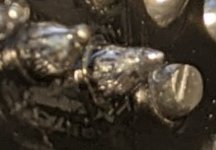
Some of the solder joints don’t look great. I’ve posted a photo of one you should definitely re do.
 

Attachments

  • 613AD599-1550-4F8E-8F6B-B1F3A2201AF0.jpeg
    613AD599-1550-4F8E-8F6B-B1F3A2201AF0.jpeg
    113 KB · Views: 6
R102 was one of the incorrect values. The board shows 680R and that's what I had. I'm curious to learn how you knew that could be an issue?
What led me to believe R102 could be an issue....
Voltages at pin 3 and pin5 of IC1 were .3 and .6Vdc. The voltage on these 2 pins are supplied by Vref, and should be around 4.5 volts with pin 5 a little higher since pin 3 has a 1M resistor on it. Vref is derived from a simple voltage divider consisting of R101, R102 and C101. Since R101 and R102 are both 47K, then Vref should be 4.5Vdc. Since R102 is the bottom resistor of the voltage divider, if its value was low then Vref would be low. I guessed at the 4k7 value, this is an easy mistake to make since 4.7k and 47k resistors have very similar color codes and if you do the math then Vref would be .8Vdc.

Voltage divider calculations

R101 and R102 both equal 47K
R101+ R102=94K
R102/94k=.5
.5 X Vin=4.5Vdc

With R102 lower: Assume 4.7K for R102 and R101 47k
R101 + R102 = 51.7K
4.7k/51.7k=.09
.09 x 9 =.8Vdc

.8V and .6V are the same to me on paper since I don't know what the Vdc in is. A battery could be lower than 9Vdc.
 
Last edited:
Back
Top