guitarplayerx78
New member
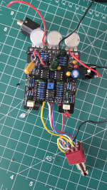
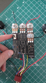
Hi, I'm building a Caesar Chorus (clone of the Walrus Julia) and I'm completely stuck at for why I can't get this pedal to work. I was able to build a separate Caesar for a friend that worked fine, but I can't seem to get this one working. I've successfully built other pedals (this is my ~6th pedal).
With bypass engaged I get my audio signal which I set to a clean sine wave for testing.
Both the rate LED and switch LED turn on. The rate LED changes with the rate pot.
My input voltage from a battery is ~8V.
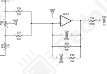
I can trace a sine wave audio signal input with an oscilloscope through the signal path and I measure it at IC3 (V3207D) pin 3. I see the clock signal as a square wave at IC3 pin 2 and pin 6. However, I don't see any sine wave signal coming out of IC3 pin 4, pin 7, and pin 8. IC3 pin 4 is at about 7.2V, and pin 7 and pin 8 are both at about 3.2V. IC3 pin 3 is at about 1.7V. Ic3 pin 4 and ic4 pin8 are continuous and I wasn't able to detect any other incorrect continuity.
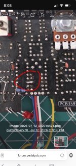
I have swapped out several components including both IC3 and IC4 (V3102D) without any change and the board is starting to get messy as I've soldered things on the opposite side to replace some of the cheaper components that i thought might be causing issues. The other recorded voltage I have from my most recent troubleshooting is: Q4 is at 1.7, 2.2, and 7.8V.
Any help would be greatly appreciated!
With bypass engaged I get my audio signal which I set to a clean sine wave for testing.
Both the rate LED and switch LED turn on. The rate LED changes with the rate pot.
My input voltage from a battery is ~8V.
I can trace a sine wave audio signal input with an oscilloscope through the signal path and I measure it at IC3 (V3207D) pin 3. I see the clock signal as a square wave at IC3 pin 2 and pin 6. However, I don't see any sine wave signal coming out of IC3 pin 4, pin 7, and pin 8. IC3 pin 4 is at about 7.2V, and pin 7 and pin 8 are both at about 3.2V. IC3 pin 3 is at about 1.7V. Ic3 pin 4 and ic4 pin8 are continuous and I wasn't able to detect any other incorrect continuity.
I have swapped out several components including both IC3 and IC4 (V3102D) without any change and the board is starting to get messy as I've soldered things on the opposite side to replace some of the cheaper components that i thought might be causing issues. The other recorded voltage I have from my most recent troubleshooting is: Q4 is at 1.7, 2.2, and 7.8V.
Any help would be greatly appreciated!