neiltheseal
Active member
Hi everyone. I am having trouble with DR Trebor from PCB Guitar mania which is the same as the Pharmacist overdrive from pedal PCB. I know I should have bought this from Pedal PCB but It wasn't available when I ordered.
If anyone can assist it would be greatly appreciated.
I get a signal when engaged and all of the pots and Mach Shau switch seem to work however the sound is quiet and very spluttery. It sounds like a transistor is not biased properly.
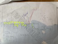
With an audio probe i can get a good signal right up to the base of q2 but the collector and emmitter aver very quiet and spluttery as is the signal from there on. If I strum my guitar very hard the signal goes from quiet to extremely loud.
I assume the problem is around q2 but not not sure how to fix it. I have swapped the transistors and the problem is still there
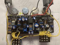
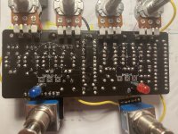
Attached are some pics. I have some resistors in series and caps in parallel to make up necessary values. However these don't seem to be where this issue is (happy to be corrected)
IC1 (LT1054) voltage:
1 - 8.9
2 - 8.8
3 - 0
4 - 0
5 - 0.18
6 - 2.65
7 - 0
8 - 8.95
q1
E - 0.18
B - 0.66
C - 2.89
q2
E - 0
B - 0.47
C - 3
q3
E - 2.32
B - 3
C - 2.43
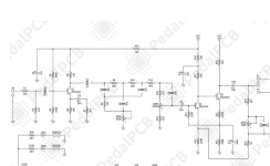
The PCBGM build docs are below. As far as I can see the schematic is the same as the pedal PCB docs (also below) except the 12k resistor from VC to r6 is connected to r16 (the other VC input) in the pedal PCB version.
If anyone can assist it would be greatly appreciated.
I get a signal when engaged and all of the pots and Mach Shau switch seem to work however the sound is quiet and very spluttery. It sounds like a transistor is not biased properly.
With an audio probe i can get a good signal right up to the base of q2 but the collector and emmitter aver very quiet and spluttery as is the signal from there on. If I strum my guitar very hard the signal goes from quiet to extremely loud.
I assume the problem is around q2 but not not sure how to fix it. I have swapped the transistors and the problem is still there
Attached are some pics. I have some resistors in series and caps in parallel to make up necessary values. However these don't seem to be where this issue is (happy to be corrected)
IC1 (LT1054) voltage:
1 - 8.9
2 - 8.8
3 - 0
4 - 0
5 - 0.18
6 - 2.65
7 - 0
8 - 8.95
q1
E - 0.18
B - 0.66
C - 2.89
q2
E - 0
B - 0.47
C - 3
q3
E - 2.32
B - 3
C - 2.43
The PCBGM build docs are below. As far as I can see the schematic is the same as the pedal PCB docs (also below) except the 12k resistor from VC to r6 is connected to r16 (the other VC input) in the pedal PCB version.
Attachments
Last edited: