I finally like to post a project I'm running a couple of months now. It's nearly done but there's still one problem left and
I obviousy don't have any clue.
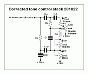
It's an IC-based emulation of a Hiwatt DR103 as a (larger) pedal. It's based on this schematic here

 www.freestompboxes.org
All in all it's working very fine and sounds are fantastic. But when I increase gain and/or the amount of input signal e.g. with humbucker or an additional boost in front I got an disturbing bias-like noise (fuzzy, starving, dying battery) noise on the top of the audio signal.
I already did a bunch of tests to locate it or get rid of it:
a) Checked connections to v bias in the feedback networks
b) Took the breadboard far away from other voltage sources + drove the circuit from a fresh 9V battery.
c) Swapped the TL072 and even the TL062 , changed the 2SK117, changed diodes.
d) took an audio probe on different Points of the circuit, starving noise seemed to apear right after IC1a (in signal line)
e) Read out voltages on both JFETS and ICs. Voltages an all pins -without increased- input seemed to be quite usual, all readings between 4.15-4.95V. Increasing the input per boost decreased voltage on the output of the first position 2SK117 and the inverting input of the TL072 temporary - then increasing fast to stabilised values as the guitar swungs out. But that's the usual effect of saturation via boost, isn't it?
f) suspicious on this deviation I tweaked different resistors in feedbacknetwork of the IC1a. Increasing the Feedback resistor (3,3K) increased gain but
no change in disturbing noise. Decreasing Biasing resistor in front of IC (1 M) increased input voltage - but this doesn't lead to vanish the starving bias noise at increased input levels.
So right now I'm kind of desperate. The pedal sounds great, but for completion it
is necessary to drive it in sweet terrain via boost or fuzz.
So I would be very very thankful for suggestions or hints and of course
good questions.
Best regards.
I obviousy don't have any clue.
It's an IC-based emulation of a Hiwatt DR103 as a (larger) pedal. It's based on this schematic here
BAJA Hiwatt DR103 amplifier pedal 9v 120318
Here is my version of the Hiwatt DR103 normal channel preamp and amplifier output stage - I have not built it as yet (waiting on some enclosures) but it should work ok :wink: cheers bajaman The master volume can be omitted if desired - simply replace it
All in all it's working very fine and sounds are fantastic. But when I increase gain and/or the amount of input signal e.g. with humbucker or an additional boost in front I got an disturbing bias-like noise (fuzzy, starving, dying battery) noise on the top of the audio signal.
I already did a bunch of tests to locate it or get rid of it:
a) Checked connections to v bias in the feedback networks
b) Took the breadboard far away from other voltage sources + drove the circuit from a fresh 9V battery.
c) Swapped the TL072 and even the TL062 , changed the 2SK117, changed diodes.
d) took an audio probe on different Points of the circuit, starving noise seemed to apear right after IC1a (in signal line)
e) Read out voltages on both JFETS and ICs. Voltages an all pins -without increased- input seemed to be quite usual, all readings between 4.15-4.95V. Increasing the input per boost decreased voltage on the output of the first position 2SK117 and the inverting input of the TL072 temporary - then increasing fast to stabilised values as the guitar swungs out. But that's the usual effect of saturation via boost, isn't it?
f) suspicious on this deviation I tweaked different resistors in feedbacknetwork of the IC1a. Increasing the Feedback resistor (3,3K) increased gain but
no change in disturbing noise. Decreasing Biasing resistor in front of IC (1 M) increased input voltage - but this doesn't lead to vanish the starving bias noise at increased input levels.
So right now I'm kind of desperate. The pedal sounds great, but for completion it
is necessary to drive it in sweet terrain via boost or fuzz.
So I would be very very thankful for suggestions or hints and of course
good questions.
Best regards.


