Hot Mess Wah Pedal Need some walkthroughs.

Ramseybella

New member
Let me first introduce myself, my name is Pete been playing music mainly guitars for almost 45 years.
Always been with effects in my chain and built a couple pedals over the past couple years, mainly beginner stuff Red Llama, Rat.

Need some help and guidance please..
So last year I purchased a torn down BIY Wah pedal form a guy off Ebay all in a bundle of wires spliced together with shrink tubing of various colors and sizes, had two black plastic stereo jacks I removed (I have new switch crafts ready).
Now I have seen what the inside of a Wah pedal should look like have a half dozen already from Vintage Vox, Thomas Crybaby, Joe Gagen and Area 51 so on..
This pedal was all FUBAR inside, more wires than necessary going places they shouldn't be going to.
Don't know what the guy was going for but I see why I got it cheap..
I cleared all the spliced together shrink tubed Spaghetti mess off the board and now I need to know how to properly wire her back to life.
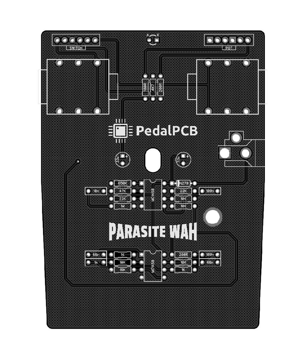
Tried to find the maker of the PCB but it has no name and couldn't find one photo of a full built board without all the wires on a socket to board layout..
The board does have marking for connection points, but since I'm not good at reading schematics I'm sort of lost!

I know this isn't Rocket Science building a standard Wah pedal, just would like to give this a voice.
Please see attached photos and if you can point out what goes where..
Thanks!


What it looked like!!
V1.jpg
Wah2.jpg View attachment 72055 Wah3.jpg Wah.jpg
 
Last edited:
With little to no information about what the board is in this pedal, it's going to tough to say for certain. I don't like making guesses and posting them for others to see, but here's a very crude wiring diagram (I spent less than 5 minutes on this) of where I'd start based on information here on the forums and on other wah projects:
1712095965054.png
Of course, wiring will not rule out the possibility that the board you have simply doesn't work. I hope this helps and make absolutely no promises that my wiring diagram is correct. Input jack is shown on left, output jack is on the right. All grounds (grd as marked on board) should be tied to a common conductor or solder point.
 
Excellent, this is exactly what I was looking for..
One question, is not the input jack not a stereo three post?
Also what it the resister size off the LED?

Thank you for going out of your way..
Pete
 
Excellent, this is exactly what I was looking for..
One question, is not the input jack not a stereo three post?
You can skip the ring lug unless you’re using a battery. If you are using a battery, a quick Google search will show you how to wire it.
Also what it the resister size off the LED?
It depends on the LED and how bright you want it. I’ve used values ranging from 1k to 22k in various builds. You are fine using 4k7 if you don’t have a preference one way or another on brightness.
 
A couple things...

1. If this were mine, I'd focus on getting it working with the minimum necessary parts. Based on what you've posted, it seems unknown whether or not the circuit works, even if wired correctly. I prefer not to use batteries in my personal builds because I don't need them (always connected to power supply) and the most common type (alkaline) isn't great for the environment. You might skip adding unnecessary parts until the circuit is at least confirmed.

2. If the circuit doesn't work after rewiring things, you might consider supporting the brand who's forum you're receiving help from. @Robert sells a couple wah pedal PCBs that will likely fit in this enclosure and have build docs.

ShamWah! : https://www.pedalpcb.com/product/shamwah/
TearJerker Wah: https://www.pedalpcb.com/product/tearjerker/
 
So wired it all up and nothing it will pass a dry signal when off but no power lights it up.
I'm thinking it maybe the foot switch as it looked a little cooked from whoever soldered it before or the 9v jack.
Time to break out the Fluke, any suggestions on where to probe first?
 
Let me know if you need more, wiring is a bit of a mess once I get it working I will tie it up.
Touched up a few sorry looking solder joints that fired up the LED but still no effect signal.
Read attachment W8 I think I found a major problem, wired the switch to one of the positive terminals of the power jack and not negative.
 

Attachments

  • W1.jpg
    W1.jpg
    349.2 KB · Views: 12
  • W2.jpg
    W2.jpg
    555.1 KB · Views: 10
  • W3.jpg
    W3.jpg
    315.2 KB · Views: 9
  • W4.jpg
    W4.jpg
    380.5 KB · Views: 9
  • W5.jpg
    W5.jpg
    405.7 KB · Views: 9
  • W6.jpg
    W6.jpg
    396 KB · Views: 8
  • W7.jpg
    W7.jpg
    500.1 KB · Views: 10
  • W8.jpg
    W8.jpg
    323.4 KB · Views: 13
Last edited:
I'm still reviewing your wiring, but right out of the gate, the potentiometer wiring isn't the same as the diagram. You are tapped on pin 3 of the potentiometer, not pin 1. I'll edit this post as I find anything else.

Edit 1: It looks like your wah potentiometer is just wired backwards altogether. Swap wires on outer pins. Pin 3 is where the orange wires are now, pin 1 is where your blue wire is.

Where is your LED? It's difficult to help in circumstances where wire is cut in places, heat shrink applied, then changes colors at the other side.

Can you get a voltmeter out and measure voltages on each pin of the switch please? Measure each pin with the pedal in bypassed state. Then measure each pin when the pedal is in active state.
 
Last edited:
The way it looked I assumed your Diagram was showing the back side of the potentiometer.
The LED wiring see attachment..
As far as the 9v input jack the attached photo am I seeing this pin layout correctly or is it backwards?
Thanks for helping me..
 

Attachments

  • LED.jpg
    LED.jpg
    505.8 KB · Views: 6
  • P-N.jpg
    P-N.jpg
    47.1 KB · Views: 6
So I wired everything according to the layout, corrected the routing mistakes wired to pot correctly and still nothing.
There has to be a dead path within the system..
Gonna give it a break for now as I'm working on another project.
May build a Parapedal out of this with fresh parts.
Had one in the 80's sounded different for sure..

But finding the potentiometer will be a challenge..
 
Agreed, myslexia is durder.


Did you ever try wiring it up without the footswitch, to make sure the circuit works?
I've read the entire thread, but may have missed if you have done so.


Here's some rudiments for understanding the DC Jack:

philmore-dc-power-jack-wiring-diagram-3 pinout.jpeg

When a plug is inserted it pushes 2 apart from 3, 3 loses contact with 2 thus disengaging the battery forcing power to be only taken from the plug.
If you're not using a battery at all, you can leave pin 3 unconnected.

Pedals are generally centre-negative:

JACK DC PINOUT.jpeg

DC JACK PINOUT outie.jpeg
 
Back
Top