How To Install A Muffin Crumb

Ginsly

Well-known member
Massively helpful member @Feral Feline hipped me to the Muffin Crumb Amplifier board (https://www.pedalpcb.com/product/6-10-6/), and it looks incredibly useful. The problem is, I have no idea how to install it connection-wise.

I was going to add it to the end of an Executive Fuzz just to see what happens, but I'm not sure how I would connect to it from the board and to the footswitch's daughterboard. I'm sure it's quite simple, but I really don't know.

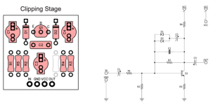
There are a few different setups for this board - Preamp, Clipping, and Tone. I assume I'd want to use the "clipping" selection, as I want to add "more fuzz" essentially, not just raise the gain/volume or add a tone control. I also want to replace one of the MC's resistors with a pot to underbias the third transistor for a gating effect- Would that be R5..? Apologies, I'm two months in- I'm still not sure how to identify which resistor is biasing which transistor in a schematic. If anyone has tips it'd help me figure out schematics as a whole. Here's the MC Clipping Setup below. It's odd, there are no values listed... I assume that's because every role will require different values, but I don't know where to start... Thanks for humoring a beginner!
Screen Shot 2024-02-04 at 2.33.55 PM.png
 
There are far more massively helpful members on the forum than myself; I manage to help out once in a while when and where I can.

SO...

CONNECTIONS

IN-JACK > 3PDT-IN > EXECUTIVE-IN / EXECUTIVE-OUT > CRUMB-IN / CRUMB-OUT > 3PDT-OUT > OUT-JACK.

Wait, that's kind of a visual jumble. In steps:

IN-JACK
> 3PDT-IN​
> EXECUTIVE-IN / EXECUTIVE-OUT​
> CRUMB-IN / CRUMB-OUT​
> 3PDT-OUT​
> OUT-JACK.​


VALUES
Extrapolate from other Muff schematics. I play bass, so I'll use the Black Russian as an example.
1) Find a black Russian schematic, such as in the PedalPCB MuffinFuzz doc and match up the values with the schematic.
You can find all sorts of versions of the Muff at Kit Rae's website.
Here's Kit Rae's example of a Russian Muff, match up the bits in the orange box to the MuffinCrumb-schematic in your OP and transfer the values (or find whatever Muff values you like and transfer those):

BLACK RUSSIAN MUFF V7_V8_BMP_Schematic—isolated muffincrumb section.jpeg


LEARNING TO READ SCHEMATICS
BuddytheReow's own guide here on the forum is excellent.

For this Executive-MuffinCrumb project, I suggest taking the boards and your DigitalMultiMeter (get a simple one if you don't have one) and put on CONTINUITY MODE where it beeps at you ⏯️🔊
Following the schematic as your roadmap, travel the traces on the board, identify each and every component on the board. Even make a printout and label the refdes of the Executive and pencil in the copper-pathways.


Further to your endeavour:
R5 will adjust the gain of the MC, you can even jumper it to GND for some massive gain, HOWEVER, if you compare the MC schematic to the BARON's, you'll find MC-R4=BARON-R10.
MC-R4 = DEATH.

I think it would be interesting to add an MC configured as clipping section to the Executive, a cool mod to the Baron Samedi.
If you want a straight up or as-close-to type replication of the Baron Samedi, you'll note there are no clipping diodes around the final transistor in the Baron Samedi schematic — it is there to boost the volume after the tone control much as a Muff has a boost stage after its tone control. So, to make the Baron straight up, you'd use the


Strictly speaking, for a 1:1 Baron, you'd have to
jumper Executive's C4,
add a cap in front of the clipping diodes (adding an extra clipping diode on one side of the antiparallel configuration,
use the Executive's volume to host the Baron's TONE pot, adding Baron's C12 4n7 across TONE 3&1, and...
TONE 1 to PCB's VOL3-pad​
TONE 2 to Baron C5 22n cap to Exec's VOL1​
TONE 3 to Exec's VOL2​

Then add the MC PREAMP as described previously.
(Preamp is simply a gain stage, what the Baron has at the end of its schematic/circuit)


Don't forget to isolate things with some electrical tape or non-conductive double-sided sticky tape, you don't want the MC bouncing around inside the enclosure and shorting something out.
 
Wow, thanks man. I figured I'd try to spare you the task of explaining this particular step to me! Ha.. I really appreciate it.

As far as the Executive>Baron goes... maybe I'll go ahead and add the MC as a clipping stage. I might as well play with some different outcomes, but I do realize it's premature for someone who can't even understand the "connections flow" you mentioned:
IN-JACK > 3PDT-IN > EXECUTIVE-IN / EXECUTIVE-OUT > CRUMB-IN / CRUMB-OUT > 3PDT-OUT > OUT-JACK.
I'm really THAT dumb (or new, I guess - but I sure feel dumb!). When you mention In Jack to 3DPT In, I'm picturing wire from the Input jack's tip to the In pad on the 3PDT daughterboard (instead of the pad to the LEFT of "In", which it would normally go to). Then you link the Exec's In pad to the Crumb's In and same thing for Out? Then link Out from the 3PDT board to the tip of the Out Jack, leaving the right pad on 3PDT daughterboard empty? See, this is probably all wrong. I'm still at the point where some of this is still a jumble, even though you probably made it very clear already! Yeesh I have some reading to do... I've seen Buddy's post before and I need to keep revisiting it.
 
Last edited:
Then you link the Exec's In pad to the Crumb's In and same thing for Out? Then link Out from the 3PDT board to the tip of the Out Jack, leaving the right pad on 3PDT daughterboard empty? See, this is probably all wrong. I'm still at the point where some of this is still a jumble, even though you probably made it very clear already! Yeesh I have some reading to do... I've seen Buddy's post before and I need to keep revisiting it.
If you are using a daughter board, it's business as usual EXCEPT you don't link the output of the executive to the DB. The exec OUT goes to IN on the MC.
MC OUT to daughter board OUT
This assumes you want the MC always on when the executive is on.
 
If you are using a daughter board, it's business as usual EXCEPT you don't link the output of the executive to the DB. The exec OUT goes to IN on the MC.
MC OUT to daughter board OUT
This assumes you want the MC always on when the executive is on.
Oh! Ok that makes sense. So I don't attach anything to the Ground or VCC pads on the Muffin Crumb?
 
Ah! I would have never figured that was the answer, so I appreciate you spelling that out.

And @Feral Feline you gave me a lot to look into, and a lot to consider. This is really helpful AND gives me a LOT to sort out:
Strictly speaking, for a 1:1 Baron, you'd have to
jumper Executive's C4,
add a cap in front of the clipping diodes (adding an extra clipping diode on one side of the antiparallel configuration,
use the Executive's volume to host the Baron's TONE pot, adding Baron's C12 4n7 across TONE 3&1, and...
TONE 1 to PCB's VOL3-padTONE 2 to Baron C5 22n cap to Exec's VOL1TONE 3 to Exec's VOL2
-Jumper C4, meaning link the two pads with a little wire. I think I got that.
-The rest is a riddle! So I:
-Somehow add a cap (value?) before the existing clipping diodes on the Executive. I'm not sure how one does that when dealing with a PCB- where does it "live" and where would it connect?
-I then add another clipping diode?
-I started to follow your instructions for using the Exec's Vol pot to then connect a new Tone pot, but it gets a bit jumbled and unclear...

Hmm maybe I'm biting off more than I can chew. I'm proud to be building functioning pedals already, but I clearly don't understand what's going on. That's not good.

Sincere apologies, this is probably all crystal clear to anyone but me on this forum! 🤦‍♂️
 
You'll need to run G and Vcc to it. Just run 2 pair wires off the DC jack Instead of one.
Aren't you bypassing the reverse polarity protection by doing that? I don't see any of that protection on the muffin crumb, or am I missing something?
 
Aren't you bypassing the reverse polarity protection by doing that? I don't see any of that protection on the muffin crumb, or am I missing something?
Yeah. and the filtering. OP never asked if it was a good idea. Just how to do it. 🤷‍♂️
Don't hook it up to the wrong power supply or you might have to replace the capacitor instead of the diode...
Or stick a protection diode in series with the vvc wire to the mc and bridge a cap between vcc and ground.
 
Ah! I would have never figured that was the answer, so I appreciate you spelling that out.

And @Feral Feline you gave me a lot to look into, and a lot to consider. This is really helpful AND gives me a LOT to sort out:

-Jumper C4, meaning link the two pads with a little wire. I think I got that.
-The rest is a riddle! So I:
-Somehow add a cap (value?) before the existing clipping diodes on the Executive. I'm not sure how one does that when dealing with a PCB- where does it "live" and where would it connect?
-I then add another clipping diode?
-I started to follow your instructions for using the Exec's Vol pot to then connect a new Tone pot, but it gets a bit jumbled and unclear...

Hmm maybe I'm biting off more than I can chew. I'm proud to be building functioning pedals already, but I clearly don't understand what's going on. That's not good.

Sincere apologies, this is probably all crystal clear to anyone but me on this forum! 🤦‍♂️
Everyone here has been where you're at.

You learn by biting off more than you can chew.

You also don't become an expert builder after swallowing the magic info-pill whole. There is no magic pill.
It's a meal to savour, take small bites, consider the flavours textures and aromas of each morsel.

Digest.

Wait until you're hungry for more before eating again.

You're already cooking up your own meals, to further use the analogy.


I've got a busy week ahead, but I'll try to draught some eyeball-examples as jwin615 did with his 1000 words post.

I suggest you print out the Executive Schematic and the Baron so you can compare the two, not on computer, on paper.
 
I've got a busy week ahead, but I'll try to draught some eyeball-examples as jwin615 did with his 1000 words post.

I suggest you print out the Executive Schematic and the Baron so you can compare the two, not on computer, on paper.
That would be incredible, and would help me visualize what's what. I'll 100% print those out and compare. Seems like there's some discussion of the Muffin Crumb connections being risky, so I'll wait a minute to order anything more. I appreciate the encouragement.
Yeah. and the filtering. OP never asked if it was a good idea. Just how to do it.
Wait, so what's not a good idea? To install a Muffin Crumb period, or to connect Ground and VCC to the DC jack in the way you recommended? I don't know up from down when it comes to incorporating a second board like this, so if there's a safer way I'd love to know. Thanks!
 
That would be incredible, and would help me visualize what's what. I'll 100% print those out and compare. Seems like there's some discussion of the Muffin Crumb connections being risky, so I'll wait a minute to order anything more. I appreciate the encouragement.

Wait, so what's not a good idea? To install a Muffin Crumb period, or to connect Ground and VCC to the DC jack in the way you recommended? I don't know up from down when it comes to incorporating a second board like this, so if there's a safer way I'd love to know. Thanks!
Ideally you filtering and reverse polarity protection.
Id be more worried about filtering out of the two.
Gnd is gnd. Hook to any gnd but I'd go straight to the DC jack for loop reasons.
There's 2 way to accomplish filtering and revpo protection.
1, pull vcc off of the executive here.
I don't think this will cause a feedback loop anyway
Screenshot_20240205-102245-332.png

2, fly a diode and cap off of the MC board
Screenshot_20240205-102327~2.png
If unitity gain is of concern to you, you may want to add a pot between the MC out and 3PDT daughter board
Hope that helps
 
@jwin615 very helpful, thank you!

The first method seems easiest- I'd leave that diode on the board and ALSO run a wire from the right pad to VCC on the MC?

The second method isn't terribly difficult, and I have the feeling it may be the "safer bet"... is that the case? It looks like the 5817 on the bottom of the MC would connect directly to + on the DC Jack, and I can connect ground from the MC to - on the DC Jack as well (or any other ground). All other Exec-to-3PDT pcb connections remain the same, looks like.

If unitity gain is of concern to you, you may want to add a pot between the MC out and 3PDT daughter board
Could you elaborate on this? It would be a passive "cut" pot, so I assume there may be "too much" gain exiting the combined Exec/MC circuit, although that is essentially what adding the MC sets out to do... This isn't something the existing Vol and Fuzz controls on the Exec would be able to control?
 
@jwin615 very helpful, thank you!

The first method seems easiest- I'd leave that diode on the board and ALSO run a wire from the right pad to VCC on the MC?
Leave the EF as is per build doc. No need for additional diodes anywhere.
When you solder that diode into the EF, don't trim that lead. Leave it to use a little of it to hook your vcc wire for the MC to. Once it's soldered, then trim it. Leave enough wire to fanagle it all in the box and be certain it won't short out.
The second method isn't terribly difficult, and I have the feeling it may be the "safer bet"... is that the case? It looks like the 5817 on the bottom of the MC would connect directly to + on the DC Jack, and I can connect ground from the MC to - on the DC Jack as well (or any other ground). All other Exec-to-3PDT pcb connections remain the same, looks like.
Yes, method 2, both G and VCC would both go directly to the DC jack. Ppcb has some DC jack breakout board for sale that would make connecting multiple wire easier/tidier. You can go to other circuit grounds but it's better practice for multiple circuits share a common ground rather than chain them together. Less chance of ground loops that way. See-"star grounding method"
No change to the plan on the signal side.
Could you elaborate on this? It would be a passive "cut" pot, so I assume there may be "too much" gain exiting the combined Exec/MC circuit, although that is essentially what adding the MC sets out to do... This isn't something the existing Vol and Fuzz controls on the Exec would be able to control?
Since your tacking the muffin crumb on the end, it is after the EF controls
You'll be able to control what goes into the MC gain stage, but not what comes out-except for the gain you set the circuit to via components.
Volume at max and volume at 50% won't sound the same except quieter. Well, they may sound real similar, it depends on how much you are clipping the signal in the EF.
You can always tack a pot on later if it's too loud.
Otherwise, your total circuit output will be set by the Vf of the clipping diodes used in the MC.
Lemme summarize, maybe. Try to follow the schematic.
In the EF, you have input trim(fuzz) gain from transistors, then diode clipping followed by an output trim.
The fuzz pot attenuates the signal before the gain stage. This, along with input signal level, determines how much the "peaks" of you signal are hard clipped by the diodes. From there it hits the output pot(vol) which is a passive attenuator. Meaning no volume added, only taken away.
So now you have your slightly squared to really squared off waveform(depending on the fuzz pot level) going into your MC. For the MC, the VOL pot on the EF is like it's "Fuzz" pot. It's attenuating before the gain and later clipping occur.
Same thing as before holds true, the louder the signal, the more squared the output. Same circuit idea. Attenuate, gain, clipping, out. But, there's no output control *except* the Vf of the diodes.
I don't think it's going to be *too loud*. Honestly, it's not going to be any louder than a EF because, well, roughly the same circuit concept(different evecution).
If you *want* a loud circuit, I'd put high Vf diodes or even LEDs in the MC. Higher Vf will= higher output.
 
Ppcb has some DC jack breakout board for sale that would make connecting multiple wire easier/tidier.
First off, this is GREAT to know. I'll be checking this out right away. Awesome!
Since your tacking the muffin crumb on the end, it is after the EF controls
AH. Ok, THIS is something I didn't consider. It sounds like the "MC Output Vol" would almost have to be an external control -kind of like the additional Master Volume control some people put at the end of a Buzzaround circuit.

I have to say, your explanation makes a lot of sense to me. I'll still have to suss out what component values/types should go on the MC, as I'm kind of lost at sea with that. I'll also have to decide if I want to use the Preamp MC model or depart from that and add a Clipping MC stage for added weirdness (?).

Full disclosure- the Exec is already built! I added a voltage starve as well, which works great for those low octaves. Couldn't have done it without this community. I love it here, even though I feel like a colossal pain in the rear.

I think I'll order another Exec (or a Teddy Rupture) when I order Muffin Crumbs, DC boards, and other helpful stuff. If I start with a Teddy, Ermahgerd, or Trumpeter I already have the voltage starve there and can then add the MC (on which I'll replace a resistor with a pot so I can bias the MC transistor to gate).

The point of this nonsense was originally to kind of fabricate a Baron Samedi out of an existing PPCB board. Feral Feline mentioned it, and it sounds like a fun challenge. I built a Baron on Vero and it's the best thing I've ever heard, I want to build 20 versions of it and mess around! Ha..

The Baron has a third transistor stage, and evidently THIS is where I'd need to bias for a pinched/gated sound. Thus, the Muffin Crumb. We'll see! If it turns out a little different than the original, maybe that'll sound great. Maybe not.

When it comes to the Muffin Crumb generally - is it just kind of expected that people would put these EARLY in the chain to avoid this issue? I mean, that would obviously affect the sound differently but I'm not sure if experienced builders just assume they'll have to add a Master Vol pot if they add it to the end- I take it they must?
 
Last edited:
.

When it comes to the Muffin Crumb generally - is it just kind of expected that people would put these EARLY in the chain to avoid this issue? I mean, that would obviously affect the sound differently but I'm not sure if experienced builders just assume they'll have to add a Master Vol pot if they add it to the end- I take it they must?
I'ta just a versatile block of circuit. Need a tone control, boost, another clipper? It's whatever you want it to be. Hoverever one wants to (ab)use it.
I think Robert may have plans to release a few more different circuit blocks. Ive thought about populating a few MCs with sockets and trimmers as well as some other smaller classics(green ringer, FF, etc) and just playing though the breadboard with them. Quickly able to reposition the "blocks" yeah, you can do it on a BB but I like the idea of fuzz modulars. Fun way to waste a few hours here and there and not a ton of parts to put up.

but it's just a common building block so how ppl use it, hard to say. It's like, how do you use salt?

I had heard /heard of the Baron. Checked out a YT demo.
Reminds me of a fuzz factory. A lot of wild/weird sounds but I have a suspicion there's a lot of unsuable knob positions as well. Have you played one?

I'm sure FF will come though with a knowledge drop on it. I'm not familiar and tracing Vero isn't fun to me. But if you have a proper schematic, I'd like to see it. I live the bosstone circuit derivatives. The Fuzzly Bear is one of my favorite fuzzes. Madbean's layout is a little smaller than the ppcb layout if you wanted to cram more circuits in a box. I think one could invert the sag pot(linear taper so doesn't matter) if so desired and make it a bit more compact. And he still has some in stock ATM(he's moving everything to a new format shortly. Don't know if this one will be around then)
I'd check out his build doc if you haven't as well.
 
Yeah, vero just doesn't work well with my brain, I don't like laying it out, building on it, tracing from it...

As much as I socket stuff, I hadn't thought to socket any MCs, I'll have to order some more! Thanks @jwin615. That'll speed up some breadboarding tasks.


Here's the Baron Samedi schematic, which was generously shared by Aditya way back when, and he has since shared what the Death pot is (thanks for hipping me to that @Ginsly) so I think it's okay to repost the schematic and Death control info here as it's clearly from Animal Factory Amplification:

BARON SAMEDI SCHEMATIC by Animal Factory Amplification w: DEATH control added.png

Well looky thar, says right on the doc to "use, modify and distribute this circuit". THANK YOU AGAIN, Mr Nandwana!

So, the Bosstone portion goes right up to the tone-control, LIFE. After that is a typical Muff recovery stage from C8 on to OUT. Compare that with the Black Russian posted earlier, to the right of the Kit Rae schematic's tone control.

What I suggested earlier, is to turn the VOLUME of the Executive into the Baron's LIFE control, that way you can just take the OUT of the Exec and feed it directly into the MC's IN. Good thing Jwin615 has covered the powering requirements, 'cause I completely skipped that tres importante aspect.


So here's how I plan on building MY own Baron Samedi:

Executive PedalPCB w: mods for Baron Samedi.jpeg
I don't have the Executive PCB yet, so do check that GND!
As mentioned, C12 gets soldered directly to the pot.
Add the Muffin Crumb with specs as per the Baron; Jwin615's diagram shows the MC's output going to the 3PDT, but I think he forgot the VOL pot:
MC-OUT to Lug-3 of a Master Vol, Lug-1 to GND, and Lug-2 to 3PDT.

I will probably bump Baron's C9 output cap to 2µ2 as mine is for

1707206910747.jpeg
 
Incredible! This is a huge step forward, although I still have LOTS of questions! Ha... @Feral Feline the schematic you're going from is a slightly older one, and it looks like there might be a few differences - I'd check it against this one (although it also doesn't have the DEATH (Bias?) control yet). At first glance looks like he changed C12 in addition to lowering R10 (which becomes the Bias control anyways), maybe some other things. Figured this might be helpful:
samedi-311214.png
A few questions (since I'm very much still learning the basics):

- first off, now I see what you meant about omitting the Exec's Vol and replacing it with LIFE. I'm a little hazy on the details (of course), but I get what you're saying. In this case, the "Master Volume" will still be set up the way @jwin615 described?

- In your Exec diagram, the pink diode section (bottom) can be any diodes?

- When you mention to check Ground on the bottom pad of the remaining 1N914 (D2) on the Exec, do you mean simply check continuity with the board's Ground pads once it's fully populated? I'm not sure when/how I'd want to check that. Again - apologies, this is how I'm learning this stuff! :)

- Adding the MC with specs per the Baron: I'm not sure where in the Baron schematic I would be starting from. Right after Tone/LIFE? If you wind up plotting/listing values for the MC, I can kind of match it up with the schematic and it'll have the added bonus of helping me understand them! Still kinda lost there.

- Where do the Starve (BURIAL) and Bias (DEATH) controls fit in to this plan? I made R5 (18k) a Starve pot on my existing Executive so I guess that covers Burial (unless the added MC also complicates that), and it sounds like the DEATH control will come off of the Muffin Crumb... I plan to get another Executive if I dare to try this project, and I have to order Muffin Crumbs anyways. The PPCB DC Jack board looks great too, but it won't work for me since I use switching Jacks (I add battery snaps).

- Would it be easier to use one of the other "Bosstones With Voltage Starve" as a basis for the Baron? Between the Teddy Rupture, Ermahgerd, and Trumpeter they seem to have that control already integrated, and some other tweaks too. You'd still need to add a Gate/Bias control and Tone, though. I guess it wouldn't be a 1:1 Baron, but maybe it'd offer those sounds and more. Just wondering.

It'd be cool to see a "full plan" diagram at some point. The ones BOTH of you shared have already helped immensely. Combining the modded Exec, the MC, and the new power setup into one diagram with values would help things click. Honestly, the only was I way able to build a Baron was because of the Vero diagram - I'm a visual artist and it's the way I understand things, at least initially. I'd be lost trying to convert a schematic to Vero or vice versa. I'm working on it, but I'm still very, very green.

@jwin615 Your comparison to the Fuzz Factory is a pretty good one, although I think the Baron has more usable settings - for me, at least. It doesn't go into crazy oscillation like the FF, and the "pinched" velcro sounds have a very different character to them. At certain settings the attack has an oddly flute-like quality, and the overall timbre is really satisfying. I love the Fuzz Factory, but since I like Bosstones better than Fuzz Faces I'm naturally drawn to the Baron.
 
Last edited:
Back
Top