

falco_femoralis
Well-known member
I did this today. I sell on reverb and like using PPCB boards for their quality, but I like to place things out differently and use big knobs, and also off board wiring sucks, so I wanted to come up with a way of building pedals that would allow me to spend less time adapting and more time producing.
Here's my Distortr build I made a while ago. I put the switches here more or less by accident, because I forgot to think ahead and see they would interfere with the PCB, and as a result I had to change up the inside of the pedal quite a bit to get everything to fit. But finding a place for switches had been difficult for me since I like to use oversize knobs, and they fit really nice here.

So I came up with this. This is my third iteration of an "everything all on the board with no off board wiring" and a "try to streamline workflow" pedal. I used the MXR Il Diavolo as a control so I would be able to listen to differences between circuit design.
My workflow involves taping up the enclosure to protect the finish, then marking a centerline, placing the knobs and footswitch on the board, eyeing it up until I like it, then marking their positions with a pencil and a combo square, then drilling them out on the drill press. The components on the PCB are quite tight, so I wanted to use the PCB as a template for the layout to reduce the error factor.
I printed centerlines for the footswitch, toggle switch, as well as one at the top of the board so I could align the board with the centerline I'd place on the pedal. The bottom edge of the board is flush with the housing of the footswitch, so I'm able to use it as the foundation for all the other markings. I cut out the bottom left corner of the board the exact amount to draw in alignment lines for the vertical position of the footswitch and the horizontal position of the toggle switch. The width of the making lines is 0.5mm, the same width as a mechanical pencil lead.
I made a circular board cutout for the tone pot so I can reach thru the board with my punch and create a pilot divot for the drill later. The other two pots have allocations for a punch as well - the board dimensions are exactly the center lines of the pots.
Making the hole for the power jack up top is inconsequential. The only part that involved actual thinking were the side jacks - their holes measured 9/16" up from the bottom lip of the enclosure and 1 15/16" up from the narrow side where the footswitch is, with the shoulder of the combo square resting on the corner of the enclosure. To establish these measurements I had to build the board into the enclosure, then take it back apart. Now that I have these measurements in the future I can just measure and drill the holes. I prefer referential measurement but I don't see a way to do that here
Here's the layout. This was much less annoying to do with the PCB as a template
Building up the board. The jacks will go in last, after the pots and switches
I put the switches and pots into the enclosure, then fit the PCB down onto them
Now we get this and I'm able to solder everything in
To install the jacks I tack solder half of one leg in, then fit the board into the enclosure, get all the measurements and drill the holes (though now that I have these measurements hopefully I won't need to do this step in the future). Then I screw the jack in place and remelt the solder so that the jack can conform to the slight angle of the enclosure side. Then I solder the rest of the pins. Same with the other side.
Here's how the alignment turned out
And it works! (once I remembered about that missing 1uF)

This is an old enclosure I'm using as a prototype. The main concession I'm making compared to how I normally build pedals are the side jacks. I tried to get top jacks to work with various designs and jacks, including daughter boards, but there just isn't room in the 1590b to make it happen without off board wiring. I did research and it turns out most people don't gaf anyway. This way I'm able to use a big plastic retaining nut for the power jack, which is more secure anyway.
I'm going to build a few more and see how the workflow is. It's all very straightforward with almost no measuring except for the audio jacks, which are a bit complicated due to the slight angle of the circuit board and the inability to locate their height with a template. But it feels nice when it just comes together and works
Here's my Distortr build I made a while ago. I put the switches here more or less by accident, because I forgot to think ahead and see they would interfere with the PCB, and as a result I had to change up the inside of the pedal quite a bit to get everything to fit. But finding a place for switches had been difficult for me since I like to use oversize knobs, and they fit really nice here.

So I came up with this. This is my third iteration of an "everything all on the board with no off board wiring" and a "try to streamline workflow" pedal. I used the MXR Il Diavolo as a control so I would be able to listen to differences between circuit design.
My workflow involves taping up the enclosure to protect the finish, then marking a centerline, placing the knobs and footswitch on the board, eyeing it up until I like it, then marking their positions with a pencil and a combo square, then drilling them out on the drill press. The components on the PCB are quite tight, so I wanted to use the PCB as a template for the layout to reduce the error factor.
I printed centerlines for the footswitch, toggle switch, as well as one at the top of the board so I could align the board with the centerline I'd place on the pedal. The bottom edge of the board is flush with the housing of the footswitch, so I'm able to use it as the foundation for all the other markings. I cut out the bottom left corner of the board the exact amount to draw in alignment lines for the vertical position of the footswitch and the horizontal position of the toggle switch. The width of the making lines is 0.5mm, the same width as a mechanical pencil lead.

I made a circular board cutout for the tone pot so I can reach thru the board with my punch and create a pilot divot for the drill later. The other two pots have allocations for a punch as well - the board dimensions are exactly the center lines of the pots.
Making the hole for the power jack up top is inconsequential. The only part that involved actual thinking were the side jacks - their holes measured 9/16" up from the bottom lip of the enclosure and 1 15/16" up from the narrow side where the footswitch is, with the shoulder of the combo square resting on the corner of the enclosure. To establish these measurements I had to build the board into the enclosure, then take it back apart. Now that I have these measurements in the future I can just measure and drill the holes. I prefer referential measurement but I don't see a way to do that here
Here's the layout. This was much less annoying to do with the PCB as a template

Building up the board. The jacks will go in last, after the pots and switches

I put the switches and pots into the enclosure, then fit the PCB down onto them

Now we get this and I'm able to solder everything in

To install the jacks I tack solder half of one leg in, then fit the board into the enclosure, get all the measurements and drill the holes (though now that I have these measurements hopefully I won't need to do this step in the future). Then I screw the jack in place and remelt the solder so that the jack can conform to the slight angle of the enclosure side. Then I solder the rest of the pins. Same with the other side.
Here's how the alignment turned out

And it works! (once I remembered about that missing 1uF)
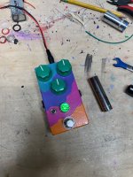
This is an old enclosure I'm using as a prototype. The main concession I'm making compared to how I normally build pedals are the side jacks. I tried to get top jacks to work with various designs and jacks, including daughter boards, but there just isn't room in the 1590b to make it happen without off board wiring. I did research and it turns out most people don't gaf anyway. This way I'm able to use a big plastic retaining nut for the power jack, which is more secure anyway.
I'm going to build a few more and see how the workflow is. It's all very straightforward with almost no measuring except for the audio jacks, which are a bit complicated due to the slight angle of the circuit board and the inability to locate their height with a template. But it feels nice when it just comes together and works
Last edited:


