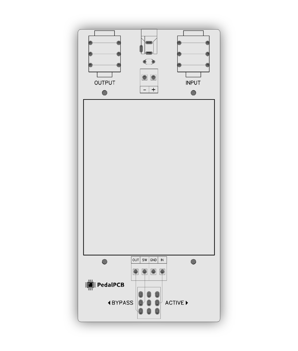
Keen to build a testing box, but something I'm battling to find answers for...

kylewetton

Active member
Hey everyone, beginner here

I'm keen to build a simple pedal testing box, I understand that in simplest terms it's offboard wiring expect you can connect 4 points to it. Input, Output, 9V and Ground.

I'd just like to clarify something though, the grounds on the circuitboard of a pedal at the top, and the one for the switch, are these here to ground the circuit board, or are they there to ground what you're connecting to it.

Here's a visual:

Green wires: The main 4 that you want connection points for.

Blue wires: Can these omitted if the 1/4" jacks and footswitch are ground inside the testing box instead? Or does a pedal require these holes to be ground to operate properly?

Orange wire: What do I do with this?

IMG_3298.jpg
 
The equivalent of the wires going to the jack in your image would all be in your test box. Inside my test box, I have two 1/4" jacks and a power jack. The audio jack grounds are grounded to the DC jack ground, and additional wires extending in/out/9V+/ground come out of it to connect to a board with alligator clips. I guess there are other ways to do it, but I think that's a simple version.

You don't need to worry about bypass when testing, so you don't need to account for all the lugs of the footswitch.
Thanks for that, so the foot switch in the testing box, I would or wouldn't be able to test if bypass is working (clean signal when the pedal is off, affected signal when the pedal is on). To clarify, does the testing box foot switch control the bypass of the pedal?
 
This (https://www.taydakits.com/instructions/1590b-enclosure-pcb) may not quite be what you're looking for but I've been using one as a cheap and cheerful tester for a long while now. It's basic but gives you ground and 9V (via battery if you prefer) or outboard PSU, in and out jacks too (obviously) :)

Reading the instructions properly, instead of just building it blind, led to a recent huge a-ha moment for me. I couldn't figure out why I was struggling to bias various circuits. I'd routinely fall 1.5-2V or so short, which naturally wasn't adequate for most BBD-based builds.

In fairness to the designer, the fine print says don't install two components (one resistor, one diode) because there's an intentional voltage drop. My newest version took this into account and the problems I'd been experiencing with a recent MBP Polytrog build (where one option was working and the other stubbornly refusing to do so) just went away. Wow, I had been sabotaging myself for quite some time ...

This old dog learnt a new trick, for sure...:rolleyes:
 
Not specific to your question but here’s the test box I built, I omitted the 2nd switch and audio probe banana jack as I just clip it into the output on the speaker terminal when I want to use it. But works great


I typically just plug the four wires you marked green from the board into a breadboard and use breadboard jumpers to go to the test box.
 
I'll hop in and suggest building something like the Test Box 2.0 from Tagboard. I used the testing platform that's sold on PedalPCB and personally found that it could be tricky to get a solid connection on the wires at times. I built something similar to the tagboard box that uses speaker terminals and it works great. Plus, it's a fun little build and feels good to have an actual solid box to hook your boards up to.
 
I know I suggested the JMK (which I have), but I've both the PedalPCB ProtoBoard Micro and the PedalPCB Auditorium and often just use the Protoboard Micro to test my PCB-builds, well, all builds perf/vero/breadboard.
 
Back
Top