
Jonathan1986
Member
I'm a complete novice in understanding schematics. Can a whiz out there let me know how to wire this up to my PedalPCB test station? The board does not label which wire holes on the footswitch are ground, in, out, switch, etc.


Duh, yeah of course I could just do that; thanks.Just use the stomp switch daughterboard and run a short 6-wire ribbon cable or some small wires directly across as shown in the build document.
Sorry, the "duh" was self-deprecating to myself, not attitude to you lolJust use the stompswitch daughterboard and run a short 6-wire ribbon cable or some small wires directly across as shown in the build document.


In fairness the build docs don't show actual wires. I'm pretty new to PCBs myself having built mostly on Veroboard prior. I have to admit I wondered about the 3PDT PCB and followed a few traces before I said "Duh! it just jumps over directly!!" Don't feel too bad!Sorry, the "duh" was self-deprecating to myself, not attitude to you lol
Yes, the Auditorium Test Platform, it's great for testing, helps so much with troubleshooting if you know your board is fine you can isolate to the wiring or footswitch to correct the issue.No worries. By the way, which PPCB test station are you using? I'm guessing it's the Auditorium Test Platform - just use the daughterboard with your build, ignore the Bypass section of the test rig and use the stompswitch on the daughterboard for testing. Given study and time, you got this.
In fairness the build docs don't show actual wires. I'm pretty new to PCBs myself having built mostly on Veroboard prior. I have to admit I wondered about the 3PDT PCB and followed a few traces before I said "Duh! it just jumps over directly!!" Don't feel too bad!
Actually, not sure this makes sense. How will I know where to run the in and out signal from the board with those are taken up by the ribbon cable on the footswitch? I won't be able to use the test platform at all if it's wired up to the footswitch??No worries. By the way, which PPCB test station are you using? I'm guessing it's the Auditorium Test Platform - just use the daughterboard with your build, ignore the Bypass section of the test rig and use the stompswitch on the daughterboard for testing. Given study and time, you got this.


How will I know where to run the in and out signal from the board with those are taken up by the ribbon cable on the footswitch?
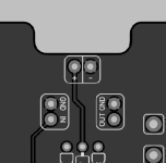
Ahh, I didn't realize the Kliche had a separate IN and OUT spot on the boards, most your boards don't. Gotcha, thank you so much!Use the IN/OUT at the top of the board, these won't be attached to anything else.
With the footswitch attached at the bottom you'll be able to test the buffered and active modes.
View attachment 122049