coltonius
Well-known member
Curiosity is getting the best of me, so I'm making an appeal to the community.
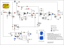
The JHS Shamrock Mod adds two toggles to a Klonlike circuit: Gain (3-way clipping) and Punch (appears to be a DPDT swapping a resistor + adding red LEDs). The former is pretty straightforward, and the latter appears to be swapping out R9. No clue what the red LEDs do, unless they're adding soft clipping somewhere? It works independently from the Gain toggle.
Any guesses what's going on with the LEDs? Perhaps @Robert or someone who's familiar with the KTR parts designations can tell us where R9 lies in the circuit.
Resources: Kliche build doc