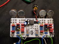
SOLVED Knight of Tone (KOT) from PCB Guitar Mania

ntuncer

Active member
Hello all,

After 2 days of trying to find the problem, I have nothing, I am desperate and really need your help. This is a PCB Guitar Mania's Kot which there is a 18v charge pump. Both switches work fine with leds, there is a sound in bypass but there is no sound when I engaged, both channels have same problems.

Result of my diagnostic:
  • I used audio probe and find that there is a sound on IC1's pin 3 and not pin 3. And checked the other pins. I found that I have voltage problem.
    • When I remove IC's and read the voltage:
      Pin 4 = 0 v as expected
      Pin 5 = 0 v it suppose to be around 9v as Vb
      Pin 8 = 0 v it suppose to be around 18v
  • When I check the power section I have 17.39v from output of D15
  • If I remove R13's one leg I have 17.39v in Pin 8 of IC1
  • I have already replaced almost everything on pover section, R12, R13 and C10 but result is same.
  • When I check the continuity from Pin 5 and 8 to ground, they seem fine nothing to the ground.
  • I have already replaced IC3 but the result is same
I am totally blocked and I have nothing to try anymore. Could you please help me to find the issue please? I have already build lots of same pedal but on this one my skills are not enough to go further.

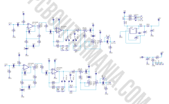
Here is the schematic:

1639904160739.png

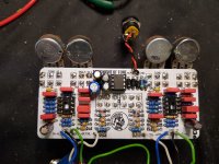
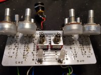
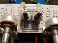
Photos inside:
3.jpeg
2.jpeg

1.jpeg

Cheers
 
Some of you solder joints look like they have very little solder, some look like they may be cold (the ones that don’t look nice and shiny). I suggest also cleaning the board with IPA and a toothbrush. Besides that, did you check the values of your components?
 
Thanks @giovanni I have already cleaned the board with IPA and a toothbrush apart the voltage part in the third picture and checked all the values. In any case I will repass the solder again all of them and share the result from here.
 
Did you check continuity between the power section (Vcc and Vb) and pins 5 and 8? That’s most likely the issue (at least one of them). Your power section seems fine. No need to replace the IC: it’s not its fault if it’s not getting the right voltage.
 
Did you check continuity between the power section (Vcc and Vb) and pins 5 and 8? That’s most likely the issue (at least one of them). Your power section seems fine. No need to replace the IC: it’s not its fault if it’s not getting the right voltage.
What do you mean by Vcc? Do you mean IC3 pin 5 as -Vc on the schematic?
 
No, Vcc=18V. Vcc is the common symbol used to indicate the largest power supply voltage available in a circuit.

Edit: in practice you should have continuity between the positive lead of C13 and pin 8 of the IC. You most likely don’t and we need to figure out why.
 
Did you check continuity between the power section (Vcc and Vb) and pins 5 and 8? That’s most likely the issue (at least one of them). Your power section seems fine. No need to replace the IC: it’s not its fault if it’s not getting the right voltage.
I just check the continuity without passing solders yet. There is a continuity between Vcc (after D15) and Pin 8 of IC1 and IC2 but there is no continuity between Pin 5 and Pin 8 thus Vcc.
 
Right but are you measuring on the pad or component leg or both? If you have continuity with Vcc but then your voltage is 0V, you are either measuring something else or your Vcc must be 0V…
 
Right but are you measuring on the pad or component leg or both? If you have continuity with Vcc but then your voltage is 0V, you are either measuring something else or your Vcc must be 0V…
Below are my contact points to measure the continuity on the pcb directly. Am I doing something wrong?
Inked3_LI.jpg
 
I think that’s correct. So what voltage do you get if you measure at pins 8 and 5 (with power on, black probe at ground)?
When I measure the continuity on the pcb, there are continuities but when I try to measure bottom of the pcb, I couldn't get any continuity. So I resoldered again the all ICs pins, both D15s on the pcb and under the pcb finally I can read voltages on pin 5 8.72v and pin 8 17.44v :) Now I will try if I have sound with ICs.
 
When I measure the continuity on the pcb, there are continuities but when I try to measure bottom of the pcb, I couldn't get any continuity. So I resoldered again the all ICs pins, both D15s on the pcb and under the pcb finally I can read voltages on pin 5 8.72v and pin 8 17.44v :) Now I will try if I have sound with ICs.
That’s great!
 
Here is the lates status. Before boxing it, it was ok but after boxing it I made a mistake cause of hurry dc plug was shorted. After fixing it there is a high pitch sound even pedal was off. when I remove the ic 2 and ic3 there is always audio signal on pin 3. I put out the pcb again but there is still that high pitch sound exists. I think I will continue tomorrow. :(
 
Back
Top