Leprechaun / Switching Jack

Calibongo

New member
Hey All
Im returning to pedals building after a few years of hiatus.
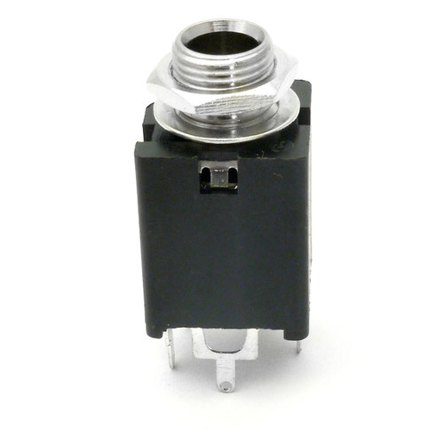
Finalizing now my Leprachaun build - I noticed that the Switching Jack I recived from Musikding is one of those 2 SPDT (meaning it got 9 pins ?!)
I see most of your buildings are with a jack having 6 pins.
But I assume I can build it anyhow with the one I got right ?
Trying to figure out what is ment by 'Switching Tip' on the schematic and cant put the dots together.
Can anyone advice me which pins needs to be solder where on the PCB ?
Attaching the Schematic of the Switching Jack from Musikding as well.

thanks!

Cali
20230314_231638.jpg 63mm-stereo-jack-with-2-spdt-switches.jpeg 20230314_231638 close up.jpg
 
Saw this in StewMac:

BC3DE398-90A5-4941-9BB8-3FD201EF4E49.jpeg

In the comments:

“The wiring diagram is not completely clear. The ring, tip and ground are not switched internally. Those terminals operate like any other jack. The internal switches are separate from ring,tip and ground. If you want to switch those terminals, just jumper the back of the switch the way you want., with a small wire. IE jump tip no 4 to common no 2 and you have tip switched out through poles 1 and 3 as you need.”

 
mmm still not sure how does the explanation apply exactly to what I need to do.
When Pedal PCB mention 'Switching Tip' - how does it differe from the normal mentioning of 'Tip' ?
is the the position of the Tip while a jack is inserted to the switch ?
What I did when I usually dont understand how switches work I use my Multimeter with the contact position to hear where there is a conduct.
When inserted a stereo jack (with Ring and Tip) - there wasa. connectivity from the Jack's tip to Lug number 4.
When the Jack was not inserted there was connectivity between 2 and 6.
So as you see - my attempt was jumpering these lugs assuming that when building the project without Expression Pedal Switching Jack - there is as well a jumper between the Tip and Switched Tip position of PCB.
Its a first build ever with a Switching Jack fro me after all (and I do not use or have an expression pedal yet, but just wanted it to have the option to use one)

thanks for your help
 
Hey @Calibongo , welcome back to pedal-building and to the PedalPCB forums.

Hmmm...

No expression jack, T as in TIP is jumpered:

LEPRECHAUN NO EXP-JACK JUMPER.png


Expression-jack wiring...

LEPRECHAUN EXPRESSION JACK WIRING.png


Let's break it down...

According to your Musikding Diagram of the switching jack you have...

Essentials:

RING = 8
TIP = 4
SLEEVE = PIN 9

So if the build without the jack requirers a jumper on the TIP, then you need the jack to BREAK the TIP jumper/connection when something is inserted.

STEREO JACK SWITCHED TIP MUSIKDING 9pin.jpg

Pretty straight forward, now we just need to work out which switched tip to use.
The "?" above needs to be...?

According to KR's StewMac diagram, which at a glance matches the Musikding's numbering (even though the StewMac and Musikding are shown in a different order, the numbering to pins themselves matches)...

The way I see it, there are two options and either one will work:

OPTION 1
PIN 4 wired to the board's "T", AND jumpered to PIN 2
PIN 3 wired to the board's "SWITCHED TIP"

OPTION 2
PIN 4 wired to the board's "T", AND jumpered to PIN 6
PIN 7 wired to the board's "SWITCHED TIP"

Whichever option you choose the other option is left unused...

It's essentially a stereo jack with two switches that can be configured open or closed. So...

Hell, you could wire up the Expression pedal on one switch and use the other for... LED indication of something being plugged into the expression jack or... hmmm...


I have yet to build my Leprechaun PCB and have never dealt with 9-pin switching jacks before. So this was a good primer for when I do build mine.

This has been quite educational for me, wrapping my brain around this type of jack, a very cool and versatile jack!

Thanks
 
Hery Feral Feline thanks for all this info!
going to recap and maintain everything next time my hands on the build.

I think I will skip the led indication for the Expression pedal being plugged.
The Switching Jack is already very challenging and for me stepping back to pedal building after a while - enough lessons learned here :)

thanks and I will update soon!
 
im wondering though and probably I would have to search in the forum for that - is there a mod to either mute out the dry signal or make an output for 100% the wet signal ? - this would come in handy when mixing / not playing the guitar. I actually wanted to experiment with this pedal on Synths / Vocals and whatever is not guitar and bass :)
 
None of the control labels seem a good fit... from the build doc:
FIRST B10K
SECOND B10K
SPECTRUM B50K
COLOUR B10K
DISPERSION B25K
REGENERATION B25K

I have one, I blame thank @Many__Of__Horror for that (MOH's build is amazerballz), but I haven't built mine yet. Haven't ordered crystals yet for the growing stack of FV-1 builds.


If one of those knobs, perhaps "SPECTRUM", were a clean-wet knob, you could do a 2knobjob switch or stomper to get your DRY-KILL.


Many_Of_Horror, is one of the controls a wet-dry mix?


If not, I'd prefer to have the schematic to suss out if there's a point where a dry-kill mod could be hacked in;
without the schematic, it would require a lot of signal-tracing and edjeamicated guesswork to make a dry kill. That's me, though.
Somebody else may have already hacked in a dry-kill — @DGWVI?
I haven't done that, but just lift one leg of R11, and connect it with an SPST (or whatever switch is convenient) then wire the other relevant lug of the switch to the pad you listed the leg from

I don't have a board on hand, but I'd lift the leg connected to pin 5 of IC1

Screenshot_20230321-175906.png PedalPCB-Leprechaun.jpg


If you wanna get fancy, and have the room, you can probably use on of the Intelligent Relay boards for a dry kill, too. In that case, I believe the lifted leg would go to the input pad, and the send pad would go to the resistor's former leg spot
 
I haven't done that, but just lift one leg of R11, and connect it with an SPST (or whatever switch is convenient) then wire the other relevant lug of the switch to the pad you listed the leg from

I don't have a board on hand, but I'd lift the leg connected to pin 5 of IC1

View attachment 44491View attachment 44492


If you wanna get fancy, and have the room, you can probably use on of the Intelligent Relay boards for a dry kill, too. In that case, I believe the lifted leg would go to the input pad, and the send pad would go to the resistor's former leg spot
thanks for the input

not sure I got you though. You suggesting 2 options to do that, have I got it right ? and excuse me as I am a returning pedal builder and all the 'hands on' know how is rusty

1. lift one leg of R11 and connect it to a SPDT (the one that got 3 lugs Im assuming ?), one end of position of the switch is the R11 leg the one one is empty and the middle (common) is connected to the position of R11 of the pcb where we lifted its leg of ?
2. lift the Pin 5 of IC1 and again same trick with SPDT switch ?

for now getting fancy is not a must or not even enough space in the enclouser I guess.
Im potentially looking for use pedals I use for mixing process and for that a 100% wet signal on a send /return chain from the mixer would be perfect!

thanks for your tips and support!

You'll only need to lift one leg of R11 and attach it to the switch of your choice
 
Yes i understand but what would be the switch toggling between? dry + wet signal OR only wet signal?

Ans so i asked with a switch - to what position does the other lug connect to? The R11 position of board?

Thanks
 
Yes i understand but what would be the switch toggling between? dry + wet signal OR only wet signal?

Ans so i asked with a switch - to what position does the other lug connect to? The R11 position of board?

Thanks
It would be a dry kill, so you'd get just the wet signal

Yes, the other lug would be connected to the hole you lifted the leg of R11 from
 
Back
Top