Leprechaun TRS jack problem

sweetthensour

New member
Hi all,
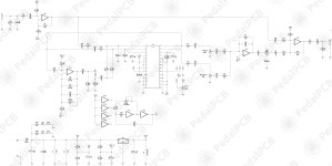
I've been having trouble with a Leprechaun build. The pedal works (I suppose normally) with the standard wiring without the expression jack, but once I connect the exp. jack, I'm not getting "that" sound, only some delayish wobble. If i turn the pitch pot all the way clockwise, usually feedback occurs. I've tried several TRS jacks but the problem remains. Maybe my CD4069 is somehow faulty? if anyone had a similar problem, please let me know. I'm attaching a schematic I found here.
 

Attachments

  • PedalPCB-Leprechaun.jpg
    PedalPCB-Leprechaun.jpg
    543.5 KB · Views: 22
If the pedal works normally with nothing plugged into the expression jack then it sounds like some sort of wiring issue. (or a non-standard expression pedal)
 
Sadly it doesn't work with nothing plugged. I didn't connect an exp. pedal, it's just not working once I wire up the jack. And i've tried multiple wirings and multiple jacks. I saw on the schematic that the exp. jack only connects to pin 20 of the CD4069, thus I wondered if that's the case.
 
That doesn’t look like a switching jack, got a link to where you got it?

Also I think you’d be better off sanding the paint off your enclosure near the jacks for proper grounding.
 
You need to pin out your jacks to see what is what because neither product you linked to has any sort of datasheet that I can find that would tell us what is switched and how. You need a TRS jack that will at the bare minimum switch the Tip. When nothing is plugged in to the jack, it should have continuity between the tip and one other terminal that is NOT connected to either the Ring or Sleeve. You can figure out what is what by plugging in a TRS cable and using an ohm meter. Once you find the tip, uplug the TRS cable and determine what other terminal it connects to, then plug the cable in again to make sure it does not make contact between those same two pins with the cable inserted. That will be the Switched Tip terminal. It's easier to visualize on a jack like this -
threaded_shaft__63230.1585326539.JPG


You have 6 terminals and it's easy to see what is what. The side facing us (the Common terminals) would be the ones that connect to the TRS pads on the PCB and the one corresponding to the tip on the other side would be the Switched Tip connection.
 
thank you for your suggestions. so i bought the switch below and this is the schematic. would anyone care to let me know how to wire it up? i currently can't get access to a trs cable and my multimeter, therefore can't proceed and check on my own as mentioned above. thanks again and sorry for the trouble
 

Attachments

  • 15948341677321058205098272657096.jpg
    15948341677321058205098272657096.jpg
    396.8 KB · Views: 22
  • 63mm-stereo-jack-with-2-spdt-switches.jpg
    63mm-stereo-jack-with-2-spdt-switches.jpg
    12.8 KB · Views: 25
You're gonna need to ID pin number 9 to orient the jack to make sure you hook the rest up correctly. Pin 9 should be the eyelet that is near the threaded part and not on the back with the rest of the connections. So with 9 facing up, the pins facing you, top right is 1, down and to the left is 2, down and left 3, down left rotate 90 4 (the pin is rotated 90 degrees, don't turn the connector, it's not a Rubik's Cube, lol), straight down rotate 90 5, up right 6, up right 7, up right rotate 90 8. I don't know how to make it any clearer than that so if you don't follow, I'm sorry. Okay, now if that does make some sort of sense, 9 = S, 8 = R, 2 + 4 = T, 3 = TN. That SHOULD work, assuming the diagram is drawn how I'm expecting it to read. I'm assuming 4 is the tip as that is how it would normally appear in most diagrams.
 
You're gonna need to ID pin number 9 to orient the jack to make sure you hook the rest up correctly. Pin 9 should be the eyelet that is near the threaded part and not on the back with the rest of the connections. So with 9 facing up, the pins facing you, top right is 1, down and to the left is 2, down and left 3, down left rotate 90 4 (the pin is rotated 90 degrees, don't turn the connector, it's not a Rubik's Cube, lol), straight down rotate 90 5, up right 6, up right 7, up right rotate 90 8. I don't know how to make it any clearer than that so if you don't follow, I'm sorry. Okay, now if that does make some sort of sense, 9 = S, 8 = R, 2 + 4 = T, 3 = TN. That SHOULD work, assuming the diagram is drawn how I'm expecting it to read. I'm assuming 4 is the tip as that is how it would normally appear in most diagrams.
It is all clear to me. Thank you for this description.
-> I got the same result when I check with a multimeter :)
 
Back
Top