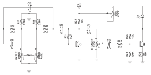
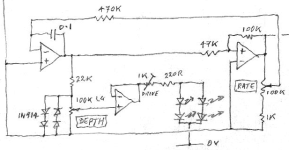
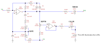
In part I, I discussed triangle wave LFOs. This time around we'll talk about sinewave LFOs. Sinewave LFOs show up mainly in Uni-Vibe type pedals, a few tremolo pedals and amplifier tremolo circuits. All of the ones I've seen are based on the classic phase-shift oscillator. To get a sinewave, we need exactly 360° phase shift at one frequency and exactly unity gain thru the amplifier and feedback loop at that frequency. If the gain is lower than unity, the oscillations will decay to zero. If the gain is higher, the oscillations will get larger and larger until clipping occurs. It's a delicate balance and it explains why sometimes a sinewave oscillator won't start up.
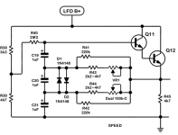
Below is the Uni-Vibe LFO. Q11 & Q12 are configured as a Darlington pair and provide the gain. C19-C21, R40-R44 and the dual C100K pot provide the phase shift. At one freq, the LFO's operating freq, the phase shift from the three R-C pairs adds up to 360°. Varying the resistance of the two pots changes the frequency where 360° phase shift occurs. The diodes provide soft clipping to limit the gain. The output is taken from Q12's emitter.
Sinewave LFOs gets kick-started when the power comes on and the sinewaves build gradually over several cycles and eventually stabilize. The designer of the original Uni-Vibe, Fumio Mieda, was a clever guy and put the diodes in a place where their clipping threshold varied with frequency. That way, the sinewave amplitude is small at low frequencies and gets larger at high frequencies. This helps compensate for the slow response of the light bulb used to illuminate the LDRs. Making C20 larger lessens the variable amplitude effect.


