Low Tide build Troubleshooting

Jdilly

Member
Just finished my Low Tide build, which isn't working for me when activated. Looking for advice on where to go next with troubleshooting. Here's some details:
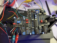
  • I'm testing the PCB currently through a test rig that I know works (rig has in jack, out jack, 9V power, and footswitch)
  • I'm connecting the in, out, power and ground from my test box to the connections on top of the PCB (there's nothing connected to the wires where you connect the footswitch)
  • When I probe the + at the top of the PCB, I get 9V. I'm also getting various voltage values at different IC points
  • I'm getting audio in bypass mode
Here are some photos of the front/back of my board.

Thanks in advance.
 

Attachments

  • Screen Shot 2022-07-18 at 10.19.17 PM.png
    Screen Shot 2022-07-18 at 10.19.17 PM.png
    1.5 MB · Views: 18
  • Screen Shot 2022-07-18 at 10.19.24 PM.png
    Screen Shot 2022-07-18 at 10.19.24 PM.png
    1.4 MB · Views: 18
First off, are the audio inputs and outputs correct? Super easy mistake to make. Second, is your volume up? Third, this project has a bias trimmer. Have you tried sweeping the trimmer while feeding audio to see if that changes anything?

If you still don’t have a signal, have you verified your parts and inspected for possible shorts or bad joints? If that checks out, do you know how to make an audio probe? You’ll need to trace the signal along to audio path to find where it’s dropping out and we can start from there.
 
Thanks.

Input/outputs are correct, volume and all pots are turned up, and I tried adjusting the trimmer while playing audio.

I'll try verifying the parts and inspecting the board more closely and report back (If that checks out, I do have an audio probe).
 
First off, are the audio inputs and outputs correct? Super easy mistake to make. Second, is your volume up? Third, this project has a bias trimmer. Have you tried sweeping the trimmer while feeding audio to see if that changes anything?

If you still don’t have a signal, have you verified your parts and inspected for possible shorts or bad joints? If that checks out, do you know how to make an audio probe? You’ll need to trace the signal along to audio path to find where it’s dropping out and we can start from there.
I confirmed the parts and checked that the joints are good, so I moved onto the audio probe. I hear audio when I touch the top input. Based on this schematic I found via Google, I tried testing R1, but aren't getting any audio. Although when I do a continuity check btw in and R2, I get a connection.

Is this the right schematic? https://docs.pedalpcb.com/project/LowTide-Schematic-PedalPCB.pdf

Any ideas where to go from here?
 
Yeah. I’m testing with a seperate test box that I built that has in/out/power/switch.

I have that plugged into the in/out/power on the top of the board.
 
You’ll need to have the input jack connected to the circuit input and the circuit output connected to the output jack. Each of the two outer pads for the foot switch connection need to be shorted.
 
That's correct. If you want to use the IN/OUT pads at the top of the board you need to add two jumpers (shown in red).

Alternatively you can omit the jumpers and connect the input to the blue pad, output to the green pad.
View attachment 29493
Thanks. If I connect the in and out of my test box to the blue and green points you highlighted, can I just leave the top in/out/grounds and other foot switch wires disconnected while testing?
 
Still no luck yet. I connected my test box to the bottom connections with the power connecting to the top (see photo), but I'm still not able to get audio beyond the input pad. Based on the schematic, I would think that R1 should be the next spot I check, but maybe I'm missing sometime.

Here's the schematic I'm referencing: https://docs.pedalpcb.com/project/LowTide-Schematic-PedalPCB.pdf
 

Attachments

  • tempImagekpN1hS.png
    tempImagekpN1hS.png
    1 MB · Views: 12
  • tempImagexk6azn.png
    tempImagexk6azn.png
    1.1 MB · Views: 12
Hey all. Got sidelined with some stuff, but back to troubleshooting. I started tracing the audio signal from the input. Here’s where I’m at so far (circle is no audio, check is audio). Should I just keep on making my way through the schematic? Meaning, there’s a few spots not getting a signal, and I’m not sure if that’s normal or not.
 

Attachments

  • B671A4A7-1E5B-4AC9-A762-8A3A430227AE.jpeg
    B671A4A7-1E5B-4AC9-A762-8A3A430227AE.jpeg
    1.1 MB · Views: 14
Back
Top