Low Tide issues with “GATE” (LPG) potentiometer function

effectism

Member
Hi all.
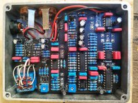
I built the Low Tide pedal “kit”.
At a first glance it works well. But I noticed something that’s strange to me. I don’t know if this happens to others.
Without any adjustment, the GATE potentiometer (LPG), acted almost as a GATE only, and not also as a variable low pass filter too (as it should). I guess that was normal, it needed adjustment.
I adjusted the “GATE” trimmer on the PCB so that the results of rotation of the “GATE” (LPG) potentiometer were satisfying for me.
But if I switch the pedal off and wait some time and then switch it back on, the “GATE” trimmer has to be readjusted. “GATE” (LPG) potentiometer acts again as a GATE only and the input signal sounds intermittently .
It seems to me that this has to do with temperature… If I “spray” (from a distance of course) the PCB with a freezer spray, or warm it (again from a distance for safety reasons) with a hot air gun, the circuit changes its behavior dramatically. This is obvious with the “GATE” (LPG) potentiometer function (only GATE, no variable low-pass filter).
Does anybody have similar issues?
I would appreciate If someone could help… IMG_20211201_101504-03.jpeg
 

Attachments

  • IMG_20211201_101504-03.jpeg
    IMG_20211201_101504-03.jpeg
    1 MB · Views: 17
A few suggestions:
  • What kind of guitar and/or signal chain is feeding the Low Tide? - I've found the Low Tide to be quite sensitive to input signal level (especially with high-output pickups or following gain pedals), so you may want to try it with both DIP switches off and see if it responds more predictably.
  • What kind of diodes did you use? - BAT48's are usually blue with a black polarity stripe, and are chosen due to their low forward voltage. Other schottky's MAY work, but may not result in the same envelope behavior on the LPG.
  • What's going on with the LPG pot pads & jumpers? - The bottom solder joint doesn't look like a reliable joint, and may be part of the problem
  • How did you set the Gate trimpot? - Here are my notes:

GATE trim pot - Setting is user preference, it controls the frequency of the low pass filter portion of the gate. “I did have to fiddle with the external gate pot on mine to get a setting where I could hear the chorusing clearly. Yyou may have to play around a little to get it completely tuned in”

GATE trim from Shallow Water Manual - LPG ADJUST (i.e., GATE TRIM) - The recovery filter’s lowest frequency can be adjusted, to fine tune the way it will react to incoming signals. Lowering this frequency emphasizes the action of the low pass filter, effectively raising the threshold of sensitivity. Adjustment should be made with the following settings: MIX full wet, LPG minimum, DEPTH minimum. While listening to a signal going through the pedal, you’ll hear the effect of the recovery filter at its resting state. Carefully turn the trimpot labelled LPG adjust (i.e., GATE TRIM), clockwise to raise the filter’s frequency, counter-clockwise to lower. Be very careful, adjustments should be minimal as the trimpot is very sensitive. After each adjustment, LPG should be turned up momentarily to listen at the envelope’s response to the incoming signal.
Hi and thanks for the response.
-The signal to Low Tide is from a rather high output "fx" loop device, It records audio from guitar or whatever and plays it as a loop with pitch control, sometimes i use only a semi hollow guitar with the LowTide
Both dip switches are off.
-The diodes I used are SD101A-TR (https://www.vishay.com/docs/85629/sd101a.pdf).
-The solder joints of the LPG pot pads are ok, the photo doesn't help a lot. I did some tests inserting resistors in series, that's why you see this "mess with jumpers".
-I set the Gate trimpot the same way that you describe. I read the same instructions you "quoted".

One last thing. I noticed in the datasheet of LM13700N (https://www.ti.com/lit/ds/symlink/lm13700.pdf page 4) that the minimum recommended single-supply configuration is 9.5V. In our case, the supply voltage is under/or 9V. Could this cause the chip to be in an "unstable" condition?
 
The high output effects loop could be part of the issue. The signal level of effects loops varies quite dramatically, but either way it's likely much higher than the tiny 200mV peak-to-peak that a guitar pedal is based around. Try it with just the guitar plugged in (out of the effects loop), if the issue is still there then it's not the effects loop causing the problem.

Those SD101A diodes have a much steeper forward voltage vs. forward current slope compared to a BAT48, especially beyond 1mA (which is likely the range in which the control circuitry is working). I used the very similarly spec'd BAT46 with no issues, but haven't seen anyone post about other successful subs. Maybe someone else can chime in on their experience with alternate diodes. I would replace those SD101A's with either BAT48 or BAT46 as they're a critical part of the envelope & creating a smooth transition between low pass and gating.

That 9.5-32V is a recommended range, and 9V is well within the reasonable operating range. There are tons of LM13700 circuits that operate on even lower V+ rail voltages, so it's likely not causing this problem, but the datasheet is always a good place to start during troubleshooting!

The Low Tide schematic hasn't been added to build doc yet, but here is a link to it. You may want to check voltages at each IC & transistor pin and post them here.
Thanks again for the reply.
I have replaced the SD101A diodes with the BAT48 ones, I found and bought them yesterday.
I tested the pedal with the right diodes (with the fx loop, with its output volume very low) but I had almost the same results.
I'll test it with other sources as you suggest even though I'm afraid this won't change something..
I already have the schematic of Low Tide that you gave me with the link (thanks for this). There aren't any voltage Test Points in it. The only known voltage (in the schematic), is at the power supply section, 9V and 5V. And of course you can measure if the voltage goes to the corresponding pin of the ICs.
I took a measure of VREF_LPG when the pedal is working ok, it is about 4.58V.
After some time with the pedal switched off (without power at all) and then switch again on, the VREF_LPG was about 4.48V. After some minutes, the VREF_LPG went back to 4.58V. I don't know if this has to do with the problem...
My main problem is that (with trims adjusted and pedal working ok) after some time without power plugged in, pedal seems to loose its adjustments. I need to wait some time, about 5-10 minutes, so I can use it without re-adjusting it. This seems to me that has to do with temperature (maybe) or the time the circuit needs to be in "stabilized" condition.

I also noticed (regardless of this issue maybe?) that the circuit is working, even if the SPDT switch is off. I mean the 9V goes to the circuit. Seems like the SPDT switch is only for the LED and the bypass functions.

Thanks again for your help!
 
It sounds as if you can reliably make the behaviour change with temperature. Does the Vref voltage also change reliably with temperature? If so then I would try and get more selective with the temperature while hooking up a meter to the Vref. try and narrow it down to a specific component if you can.
 
It sounds as if you can reliably make the behaviour change with temperature. Does the Vref voltage also change reliably with temperature? If so then I would try and get more selective with the temperature while hooking up a meter to the Vref. try and narrow it down to a specific component if you can
Ok thanks for the response i will check it
 
Back
Top