Low Tide Modulation Behavior Troubleshooting/Tuning Questions

Depattern

Member
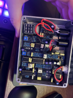
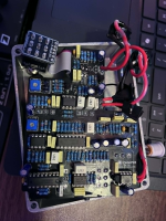
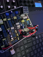
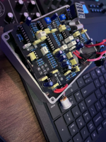
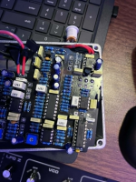
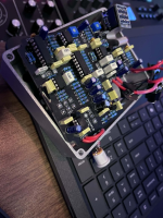
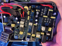
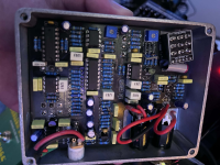
I've been a fan of the Shallow Water for a long time but never tried it. So i think i know what the expected sound should be,but Im having some major issues here with mine:


1. I hear pretty much 0 modulation unless I manually modulate the amplitude of the incoming signal (outside of the pedal). So here im sending in triangle waves from the sh-101 clone, and the only time i hear modulation, is when i tweak the volume on the synth going into the pedal. when i do that, its pretty extreme, but I cant get that effect otherwise.

when i dial the BBD BIAS pot, it goes from very noisy buzzy fuzz to nothing, then an extremely short range where i almost hear a pitch warble when turning it at a certain point, but nothing obvious. like i can hear the slight pitch drift as i turn from one increment to another very small increment, but its only audible int hat specific range and ONLY when im turning the trimpot.

i can see where the behavior might be sort of intended where the pitch modulation reacts ONLY to your playing dynamics, and i guess there isnt a wide dynamic range coming from the synth notes, but you'd think i would hear a difference in depth and rate from the lfo either way

2. the MIX effected sound is only within the VERY last like 5% of the MIX knob range. I only hear effected signal at the extreme clockwise end of that knob. I dont know if this correlates with the gate tuning or what, but i've experimented with that pretty extensively I feel like

3. The DEPTH, RATE, SLEW dont seem to have any effect. I am hoping that these modulation issue can be solved if i keep working away at tweaking the BBD trimpot, but it just doesnt feel like thats going to work

4. The gate itself is not as easy to figure out whats going on. I hear when it kicks in if i set it a certain way on the trim, but its not exactly "low pass filtered"/watery to completely open, although i do hear the lo pass effect and when the BOOST switch is set, it does behave like a low pass vcf envelope, or a real lpg sort of, but its a little tricky to determine what the actual range should be. not too worried about this one, but im just not sure whether or not this is tied to the problem im experiencing with the lfo modulation

I have probably not read through every troubleshooting thread about the Low Tide here but Im working my way through them and I have read a decent amount so far, including @Jachiro's extremely helpful post about tuning the trimpots

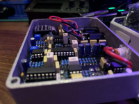
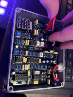
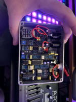
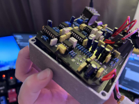
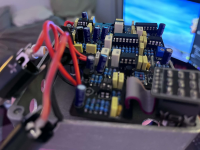
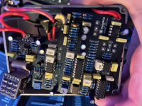
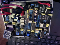
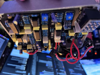
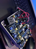
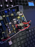
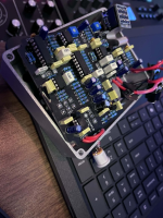
1782002158887.png 1782002166750.png 1782002184396.png 1782002184432.png
 
Last edited:
I believe this could be a fault in the randomizer IC. I don't think I can order them individually from PedalPCB though. Is there a recommended source for additional LM258P's?

I worked through the entire signal chain with a multimeter to isolate the fault:

1. IC6 (CD4046BE) pin 16: 5.05V - correct, chip is on the regulated 5V rail as expected
2. IC6 pin 4 (VCO output): 2.46V - clock is running
3. IC7 (V3207D) pin 3 (clock input): 1.703V - clock is arriving at the BBD
4. IC7 pin 4 (Vgg bias): 4.72V - BBD bias is correct
5. IC4 (LM258P) pin 7 (op-amp output to IC6): 1.782V fixed - does not change with RATE or DEPTH
6. IC4 pin 3 (non-inverting input, RANDOMIZER signal in): 2.36V fixed - does not change with RATE or DEPTH
 
I would recommend getting most if not all chips whenever possible from Mouser or Digikey. LM258P chips are made by Texas Instruments and are currently in production if I’m not mistaken. It’s the older discontinued chips that are at higher risk of getting bad chips or fake ones if you get them from eBay.
 
Is it likely at all that this randomizer is bad? It seems to be the issue from what I can tell
You can test the randomizer (IC2). Multimeter set to DC, measure pin 5 to ground, it should ramp up and dwon somewhere arounds 1 to 3 Vdc, faster and slower by changing the rate pot.

If it works, measure the BBD pin 2 or 6 AC to ground, should see around 10 maybe 100 millivolts ramping up and down.
If nothing there, IC6 pin4 same thing. If nothing there, do back to IC5 pin 7, look for either ac or dc volts ( I can't remember) going up and down.
 
Thank you for that, thats extremely helpful

i am getting 1-3 on ic5 pin 7 and ic2 pin 5. but the A1m dual gang SLEW pot bottom outer legs are only sweeping from 0 to 324v. while the top outer legs sweep from 0 to 1m.

i dont know if this is a fault with the dual gang a1m pot from pedalpcb OR something to do with r39. i dont want to pull out r39 if i dont have to, so i wanted to ask for advice here first, to make sure im even looking in the right place. should i try pulling out the A1m, ordering a replacement and testing that? should i rip out/clip r39 and replace that? i checked the stripe pattern and its the proper markings for a 470k resistor for R39. is there somewhere else i should be testing?

If i go through this circuit with my audio probe, what am i looking for?

there shouldnt be any cold joints or anything like that. ive been very careful about that any hadnt had any such issues in my last 6 or so builds.

TO RECAP:
  • DEPTH, RATE, SLEW have no effect on modulation
  • MIX wet signal only present at extreme CW end of knob
  • LPG responds correctly to input amplitude changes
  • No continuous pitch drift/LFO behavior

What I've confirmed working:

  • RANDOMIZER (IC2) pin 5: ramping 1–3.33V continuously, speed changes with RATE
  • IC5 (MCP602) pin 7: oscillating between 1–3V on its own
  • IC6 (CD4046BE) pin 16: 5.05V (correct, on 5V rail)
  • IC6 pin 4 (VCO out): 2.46V
  • IC7 (V3207D) pin 3 (clock in): 1.703V
  • IC7 pin 4 (Vgg bias): 4.72V

Where the signal dies:

  • IC4 (LM258P) pin 3: stuck at 2.36V regardless of RATE, DEPTH, or SLEW position
  • IC4 pin 7: stuck at 1.782V, does not vary

The modulation signal is confirmed alive at IC5 pin 7 but is not reaching IC4 pin 3. Between those two points per the schematic I have SLEW 2 (second gang of the A1M dual-gang) and R39 (470K).


What I've checked in that section:

  • Reflowed all solder joints on the SLEW pot - no change
  • R39 color bands read correctly as 470K (yellow-violet-black-orange-brown)
  • In-circuit resistance between SLEW 2 output leg and IC4 pin 3 reads ~490Ω unpowered - suspiciously low but may be circuit loading
  • In-circuit resistance across SLEW 2 outer pins reads 26K–324K sweeping CCW to CW - also suspicious but again may be loading from surrounding circuit
  • No visible solder bridges anywhere in that area under magnification

    I also swapped out the ic 2, ic4, and ic7 just to be sure, before i got these final results. all ic's are socketed.

I'm hesitant to start lifting component legs without being more certain of the fault location. My audio probe wont be helpful for modulation signals, i imagine. Has anyone seen this exact symptom: signal alive at IC5 pin 7 but dead at IC4 pin 3, and can point me to what to check next?
 
Last edited:
continuity check the traces around the lm258 to other parts of the circuit. some ppl have had traces break.
so it looks like the right leg of R39 was sticking out too far and even though i used those plastic caps to cover the pots, the dual gang slew pot inner holes for the second set of legs was making contact with it

so i swapped it out just in case, cut the leg, put electrical tape over everything, and im still not getting continuity from that leg to anything. although i am finally getting continuity from the left r39 leg to pin 3 of ic4

but absolutely zero effect from the pedal no matter what the dipswitch or knob positions or trimpots, aside from the lo pass gate opening up, i can hear that. its not as prnounced, like an envelope/actual lpg style gating as it was before, in my video demo. and im not getting ANY modulation, even when manually modulation the gain of the incoming signal, no matter where i put the bbd trimpot. it only goes from distorted to nothing to distorted again, almost like a thinning square wave clipping pulse near the end of the fully cw turn of the bbd trim, but doesnt actually do anything

so im kind of at a loss here. i may need some basic troubleshooting ideas

i really dont want to do this one over but i also dont want to give up. i finally bit the bullet and pulled the pcb out which is how i discovered this, after testing continuity from r39. but im not sure what to do next
 
i may need some basic troubleshooting ideas
If a pedal is passing signal but not behaving as expected I always start with a a full component check.

I print the build doc and highlight or check off each part as I go, cross referencing color codes and cap codes against what should be in each spot.

It also serves as a good general visual inspection.

If you post very clear well lit pictures where it’s easy to read the color codes, you can sometimes get some help with that step, but with a circuit this big that’s tougher.
 
If a pedal is passing signal but not behaving as expected I always start with a a full component check.

I print the build doc and highlight or check off each part as I go, cross referencing color codes and cap codes against what should be in each spot.

It also serves as a good general visual inspection.

If you post very clear well lit pictures where it’s easy to read the color codes, you can sometimes get some help with that step, but with a circuit this big that’s tougher.
i do this as i go, so i guess i should just use the same build guide for cross-referencing and reviewing every step in the process again.

I appreciate the advice here, thank you guys for your help

it's in worse shape now. after trying to manually test some bridging between r39 and ic4 for about 2 hours, i got frustrated and starting poking things like i was circuit bending. now it just sounds like a broken octave fuzz or something. might not be too terrible, because the bbd was sounding like that somewhat when biasing the bbd trimpot, but now it sounds like that all the time, no matter what, when mix is full ccw. still no audible/apparent depth, slew, rate effect. still seems like the lpg is working.

Update: After extensive, but clueless testing I've found the following:

  • IC2 pin 5 ramping 1-3V correctly
  • IC5 pin 7 oscillating 1-3V correctly
  • Modulation signal confirmed arriving at IC4 pin 5 (not pin 3 as I originally thought)
  • IC4 pin 7 output static at ~1.83V - not following the input
  • IC4 pin 8: 9V, pin 4: 0V - chip is powered correctly
  • Resistance between IC4 pin 6 and pin 7 reads 79Ω - seems too low for what should be a high-impedance feedback network
  • No visible solder bridges around the IC4 socket area
*(i also swapped out ic4 again just to be sure. pretty much the same behavior as before)

Is 79Ω between IC4 pins 6 and 7 with chip removed indicative of a specific fault? And could a component in the R64/R63 feedback network cause this?
1782930041624-png.120038


1782929966739.png 1782929978700.png 1782930012673.png 1782930012715.png 1782929985021.png
1782930054601-png.120039
1782930073664-png.120042
 

Attachments

  • 1782930054601.png
    1782930054601.png
    2.3 MB · Views: 49
  • 1782930055108.png
    1782930055108.png
    2.2 MB · Views: 2
  • 1782930055175.png
    1782930055175.png
    2.5 MB · Views: 2
  • 1782930073664.png
    1782930073664.png
    2.5 MB · Views: 50
  • 1782930074143.png
    1782930074143.png
    2.2 MB · Views: 1
  • 1782930074188.png
    1782930074188.png
    2.5 MB · Views: 1
  • 1782930041624.png
    1782930041624.png
    2.5 MB · Views: 39
  • 1782930028065.png
    1782930028065.png
    2.5 MB · Views: 1
  • 1782929998258.png
    1782929998258.png
    2.7 MB · Views: 2
On my build IC4 pins 6 to 7 measure 79 ohms, so that's normal.

I just reread one of your posts, my bad, I meant continuity on IC5.

Ok I have my pedal/schematic/layout in front of me. Turn depth all the way up, and IC2 (randomizer) pin 5 clock signal should be seen at IC5 pins 1,3,6,7 and IC6 pin 9.

IC7 (BBD) pins 2 or 6 measure AC to ground should have a small milli voltage ramping out of IC6 pins 2 and 3. I measure between 8mvac and 180mvac to ground

Out of IC7 pin 7 with no signal input into the pedal, there is a tiny ramping acv to ground around 5 to 10 mvac
 
Last edited:
thank you so much for taking the time to investigate for me. I really appreciate all of your help and motivation in this thread

I got it working, but i think when i was prodding around and getting frustrated, i may have blown something:


i completely hear the full effect. mix, depth, slew, and rate are all clearly operational and working as intended. so the pitch modulation lfos, randomizer, and bbd are definitely working great. the LPG is clearly working as well. but even with a low signal like a clean guitar, even with BOOST of and PAD on, theres this blown out distorted tone on the affected signal. and its only present when the effect's wet mix is audibly affecting the signal. i can turn mix down and get a cleaner signal, but then that also reduces the entire effect

so i know i stressed the board out when i was probing and jumping random points on the pcb during troubleshooting. i just dont know what exactly i did, how to diagnose it, or if it can be fixed. its such a cool effect and i like it a lot, even as it is. but it is very far from ideal if i have this overblown clipping breakup which is not the musically pleasant kind of kind of ruins the effect of the pedal

1st, i want to make sure this isnt intended. I know it has some jfet saturation or whatever when boot dipswitch is enabled and level is cranked, but this doesnt seem like that

2nd, I want to figure out what, if anything, is worth replacing. I dont mind replacing things here, I just need to know what to try. would it be the 2SK208Y, or would it be the J201 jfet? would it be one of the 2n3904s or even one of the ic's? is there an easy way to determine that? and would a multimeter or audio probe be a good tool for investigating the root cause of the issue in this instance

*As far as the fix goes, Im not sure what ultimately fixed the initial issue of no audible effect at all (intended effect, i've heard the blown out distorted sound since i messed with it and beat it up that day while troubleshooting. also when cranking the bbd trimpot, it would produce this sort of blown out sound). I did a bunch of things today before testing again. i swapped out the Slew A1m pot for a new one just in case, i cleaned the flux off the board, I replaced 4 ics: IC7 (V3207D - BBD Delay IC), IC2 (Randomizer), IC4 (LM258P - Dual Op-Amp), & IC6 (CD4046BE - PLL), and i reflowed almost every single trace on the bottom of the board. I think some of the hot glue (im almost positive i didnt use superglue) released whatever gas it releases and coated everything in dull residue and many traces looked awful. so thats what im betting on, but it very likely could have been any of those as far as i know

1784492155813.png I really like the effect im hearing, i just wish it wasnt coated in this disgusting blown out distortion. this build took a long time to source, build, diagnose, and fix. and I dont want to have to build a new one if at all possible

Any Ideas?
 
A photo of the underside of the board would be beneficial.
Yeah I forgot to take one while I had it out

But I think it’s fine

Either it’s fine, I need to tweak the bbd trim again, or I need to tweak the lpg

But what’s weird is that it works perfectly with a synth. So I’m assuming it’s an impedance issue. I can’t imagine more people don’t complain about it, if that’s the case since this is a guitar pedal in this iteration. But I’m leaning more towards maybe the bbd needs tweaked differently for guitar vs synth. It’s hard to adjust it with guitar since you have to play and subtly tweak simultaneously

Anyway, I don’t need it for guitar really, I think it would be better on my mixer send, and the guitar also runs through that in addition to the amp, so that may work as well

Here’s what I got:

The guitar-only distortion is almost certainly an impedance/level thing, and it’s expected behavior for this circuit. Here’s why. A guitar (especially straight in) is a high-impedance source with sharp, high-crest-factor transients — the pick attack has instantaneous peaks far above the average level. The BBD in the Low Tide has very low headroom (well under 1V), and the wet path clips those transient peaks hard. Your synth, even at “max volume,” is a low-impedance line source putting out a steady waveform with a low crest factor — the peaks aren’t much higher than the average, so nothing clips. That’s exactly why the synth sounds clean and the guitar doesn’t, even though the synth is “hotter” on paper. Average level isn’t what clips a BBD — transient peaks are.

The only thing now is that I need to get a wider range on the lpg as it’s a small sliver of useful value range on the ccw end for that lo pass filtered woozy effect to combine with the random skewed pitch modulation
 
alright im an idiot. the overblown fuzz effect was just the bbd setting. i dont know why i thought i had adjusted it already. id done it so many times prior that i thought it was still in the sweet spot and was afraid to touch it. but all i had to do was tweak it and now it works perfectly on guitar and synth and everything

so it turns out that what fixed this was the most basic steps:
-pulling out the pcb and reflowing the underlying solder points
-recalibrating trimpots once everything was finally working properly

hopefully i learned my lesson this time

thanks again for the help here
 
Last edited:
Back
Top