SOLVED Low Tide Modulator - No "wet" signal

grahjm2a

New member
Hello all!

I have a Low Tide Modulator that doesn't seem to be passing any "wet" signal through the MN3207 BBD. I do get the "dry" signal through that doesn't pass through the BBD when the pedal is engaged.

I suspect the root of the problem is the cheap MN3207s that I found via Ebay and decided to try. Unfortunately don't have any known good ones with which to compare. However, with the voltages I'm seeing at the output of the BBDs lead me to believe they are not good.

I'm disappointed that the schematic doesn't seem to be included in the build docs for this yet. If it were, I feel I could be more self sufficient with troubleshooting this, but I unfortunately don't have the pedal background to know where to go from here. Any insights from you guys are much appreciated. (I am an EE, don't have much pedal building experience. A couple of overdrives prior to this one).

In more detail:
  • Pedal bypassed works as expected
  • LED turns on/off with bypass as expected
  • Volume/mix control works when pedal is engaged. With mix low, I can hear the "dry" signal come through as expected. Turning up mix fades out the dry signal, but there is no BBD'd signal coming through.
  • Voltages as measured by a DMM are attached as a CSV/text file, voltages measured at ICs and transistor nodes attached.
    • Knobs when these measurements were taken were as follows:
      • Rate max
      • Damp min
      • Depth ~70%
      • LPG max
      • Mix Max
      • Volume ~50%
      • Gate ~50%
      • Bias ~50%
    • The outputs of the BBD measure near GND, which unless I'm misunderstanding how the BBD functions is not correct. I've verified there is not a low impedance path to GND from those pins. I would have expected to get a voltages similar to the sampled input signal voltage here if I understand what this should be doing.
    • I unfortunately don't have on hand an audio probe nor cable I can cannibalize to make one. I'm making enough pedals now though that if I need to, it's probably worthwhile to do so if I'm misunderstanding what the BBD
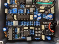
resized_PXL_20210927_153814380~2.jpg
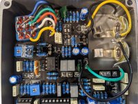
resized_PXL_20210927_153841196.jpg
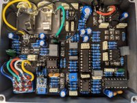
resized_PXL_20210927_153855439.jpg
 

Attachments

  • LTM_voltages.csv.txt
    2.9 KB · Views: 73
That voltages file is a troubleshooting dream, man...

I think you're right about it being a problem with the BBD stage, everything else looks fine (except for the 2SK208, but I think drain & source readings might just be switched). Here are some suggestions:
  • Pin 4/Vgg is the MOSFET Gate bias, and should be ~14/15 Vdd - around 4.7V in this case. As yours is around 0V, that may mean your BBD isn't biased & clocked properly, so I'd check the values of those two voltage divider resistors (R34/35).
  • Your MN3207 doesn't look obviously fake or anything, so that's encouraging. You can always try removing it & jumpering pin 3 to pin 7 to bypass it all together. That will allow you to check that the LPG pot, Mix pot, & Gate trim are all set up & working. The Gate trim has a kinda narrow usable range, so try turning that up.
Probably not a problem, but worth looking in to:
  • You have both the Pad & Boost DIP switches on, which may be affecting your ability to trigger the LPG. I'd try it with them both off, or with just the Boost on.
  • Your MCP602 voltages look right, but it does have that "blown IC" look to it with the yellowish residue & the text burnt off. You may want to pop in another one if you can.
 
Thank you for the advice @bowanderror.

I should have thought to bypass the BBD, I'll give that a try. I think between that and the link to the schematic that @PedalPCB passed me, I can be more effective when I have time to resume troubleshooting.

I will update with more info either tonight, or possibly later this week when I'm able to look into this further.
 
what dmm are you using? does it output a file for you?
No, I built that by hand using a generic DMM.

I took written notes on my workbench, and turned them into a spreadsheet where I could look at datasheets and measurements side-by-side. I was assuming I may need to reach out for help, and wanted it in an easy to share format.

I also work as a HW engineer, and know how to compile and communicate these kind of findings with peers when needed.
This is something beginners could benefit from learning. Keeping track of changes/substitution, connections to double-check, and the function of each component makes troubleshooting soooo much easier.

I do the same for each build, with spreadsheet containing the BOM, pin voltages, + any math I may have done on mods/subs. Guitar pedal circuits are generally simple enough to easily sim in LTSpice as well, which gives you a reference for operating voltages & gain/frequency response if you need an audio probe.
 
Looking more carefully around pin 4 of the BBD did indeed reveal a scary issue.

Apparently I got my parts bins mixed, and everywhere that should have a 4K7 resistor actually has a 4R7 resistor. Yikes.

Looking through the schematic at things that might have been stressed by too much current with that error, I may replace Q3, but don't see any other potential damage I could have caused.

(Though the BOM calls for a 4K7 effect LED bias resistor, I used a clear LED and substituted a higher value one, so the effect on LED didn't die in a blaze of glory that might have made me realize the mistake earlier).

I'll update again after fixing that on any other findings.
 
Apparently I got my parts bins mixed, and everywhere that should have a 4K7 resistor actually has a 4R7 resistor. Yikes.
Oof, good catch!

Hope your components survived, fortunately the rest of the wet signal path looks good based on voltages. Vgg/pin 4 feeds only the gates of the MN3207 internal MOSFETs, so having fed it a much lower bias voltage (with very little current available...) it's probably OK.
 
I had the same problem and just got it working last night. I could get some random modulation to the gate control, but no chorus effect.
Here's what I did.

1. Replaced the cheap MN3207 I got from eBay with a more expensive Coolaudio V3207D from eBay
2. Top soldered every resistor to make sure of no dry joints.
3. Very carefully trimmed the gate and BBD trimmers. It won't work unless both trimmers are in the correct position.

When trimming I had the controls in these positions:
Depth: max
Level: 75%
Slew: min
Mix: 50%
Rate: max
Gate: 25%
Pad: off
Boost: on

I forgot to take note of what the trimmer positions were, was so excited to finally get it going !!!

But I definitely recommend spending a bit more time on the trimmers, as mine only worked in a very limited range, and required both to be in the correct position to get the chorus effect to work.
 
Very carefully trimmed the gate and BBD trimmers. It won't work unless both trimmers are in the correct position.
Agreed. There is a pretty narrow usable range, especially on the Gate trimmer.

I just posted this on another thread, but here is info I've collected on setting the trimpots:
  • BBD/BIAS trim pot - Similar to the pot on a CE-2 or Caesar. Adjust for the least amount of distortion with modulation. Pretty obvious when set correctly. Set the Depth to 100% and turn up the output loud enough to clearly hear the signal. There is a range on the trimmer where you will hear the chorus/delay effect. At either end of the range, there is quite a bit of fizz. Just set the trimmer for the least noise.
  • GATE trim pot - User preference, it controls the frequency of the low pass filter portion of the gate - Set MIX to 100% wet, LPG 0%, Depth 0%. Turn Gate Trim CW, you should hear the filter "open up" as you turn it up. You want to set the Gate Trim so the LPG knob goes from completely off at 0% to completely open at 100%, with a good amount of different settings in between - “I did have to fiddle with the external gate pot on mine to get a setting where I could hear the chorusing clearly, you may have to play around a little to get it completely tuned in”
GATE trim setup from Fairfield Shallow Water Manual:
  • LPG ADJUST (i.e., GATE TRIM) - The recovery filter’s lowest frequency can be adjusted, to fine tune the way it will react to incoming signals. Lowering this frequency emphasizes the action of the low pass filter, effectively raising the threshold of sensitivity. Adjustment should be made with the following settings: MIX full wet, LPG minimum, DEPTH minimum. While listening to a signal going through the pedal, you’ll hear the effect of the recovery filter at its resting state. Carefully turn the trimpot labelled LPG adjust (i.e., GATE TRIM), clockwise to raise the filter’s frequency, counter-clockwise to lower. Be very careful, adjustments should be minimal as the trimpot is very sensitive. After each adjustment, LPG should be turned up momentarily to listen at the envelope’s response to the incoming signal.
 
Sorry to hold everyone in suspense; I haven't had a lot of spare time over this past week until today.

I've replaced all of my accidental 4R7 substitutions above, but still didn't get any "wet" sound out.

I bypassed the BBD (pin 3 to pin 7), again with no change.

I'm still suspicious of my BBD. With the corrected resistors, pins 7 and 8 are measuring ~15-20mV with the pedal on, but if that were the only problem, the bypass should have let something through.

My next steps were to try to eliminate things I can think of which may cause this lower than expected BBD output voltage to happen:
  1. Low impedance from pin 7/8 to GND. I've verified that the impedance coming out of those nodes are as expected given R58 through R61.
  2. Clocking failure, so that no signal is getting passed through the BBD. The DC levels at the clock inputs look right (~1/2 of VDD), and I can see there is some AC signal on them (60mV to 100mV on my DMM in AC mode). I wish I had a scope at home, maybe I can sneak the pedal into work and check that more.
  3. Broken BBD (at least the output driver). I grabbed 3 more from my suspect Ebay batch, and after applying power, had one get really hot and start to melt the corner of the chip's potting material around pin 8, and 2 others that behaved like the first one. I'm not sure what to think about that yet given that it still didn't work in bypass, but I am worried I have all bad parts.

I probed around a little bit looking for a short in this audio path, but haven't found it yet and I'm about run out of time this evening.

From here, I could try to bypass more stages. I'm not sure about bypassing the LM13700N though. Removing it and jumping the socket from pin 3 to pin 9 looks like I'm going to lose a lot of signal to GND through R28.

I think my next step is using an audio probe to trace the signal path. I'm working on getting that set up next, but am waiting on items to arrive.

Let me know if anyone is seeing something I'm not.
 
Last edited:
LM258P
Pin2: 2.01V
Pin5: 4.15V
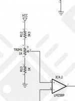
Battery used for testing is about 8.7V, so they are only ballpark figures for setting the trimmers.

I'm confused by your pin 5 voltage @Detrital.

1633307330172.png

The max you should see on pin 5 with the resistive divider, is 8.7 * 2 / 5.3 = 3.3 V. Either your voltage is much higher than you think it is (more like 11V), or you have a different value resistor in there than the schematic is showing.
 
Last edited:
I think I've been able to sort it out.

With the help of an audio probe, I could tell now that the audio signal was indeed not making it through the BBD. I was also able to hear that the gate trim setting was preventing me from hearing pedal output at all from when the I tried to bypass the BBD previously.

I ordered alternate BBDs from a more reliable source, and with those replaced (and the earlier resistor mistakes fixed as well), I now have a working pedal.

Thank you everyone for your help with this.

I'm tempted when I have time to try to do some analysis on the suspect BBDs that I originally ordered. I have a few more reputable ones now, and I can see there there is a subtle marking difference as well. I'll create a new thread sometime in the future comparing the two.
 
Back
Top