M800 - No Volume

DrumBuster

Member
Hello everyone, after neglecting my project for almost a year, I finally built my M800, when trying it out, I noticed I had no volume. Bypass works great, j201s all biased to the right voltage (4.5v ish) save for one of them not doing it. It stays stuck at 2.7, is it possible that is the culprit? I got a 2N5458 just in case is a faulty transistor. I check every solder and ground and everything seems fine, led lights up. What it can be the issue? Thanks
 
Kinda late here but here's some pics I took a few hours ago, it's my first project and is quite messy, sorry.
 

Attachments

  • pcb 2.jpeg
    pcb 2.jpeg
    41.7 KB · Views: 22
  • image0.jpg
    image0.jpg
    50 KB · Views: 23
The one Trimmer is the Tone control, this effects the pedal greatly for overall Final sound per Amp being used!
You really need to sort out that ''Rats Nest'' going to the Footswitch, Way to much to figure what's going to what!
 
Lets start with the basics,
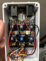
1. All your wires are too long. These need to be shortened, they will act as antenna when the circuit is working.

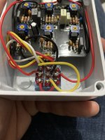
2. Look up "Tinning Leads" or "Tinning Wire". Prior to soldering wire, the stripped leads need to be tinned. This helps the solder flow better when soldering wires to board or lugs. It also prevents bird caging of the wires when inserting them in the PCB holes.(power gnd to pcb and input jack to pcb wires exhibit this.)

3. When soldering wires to the PCB, get the insulation as close to board as you can with out touching the board, exposed wires are an easy path for a short. Once you do this a few times you will get it down.

4. Even with the rats nest of wire, something looks off about the 3PDT foot switch wiring. Double check this.

5. The enclosure is not grounded. Take a Dremel tool and remove the powder coating on the inside top wall of the enclosure. Now the ring of the input and output jacks will ground the enclosure.

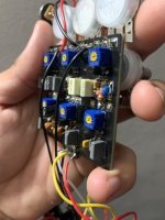
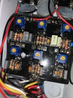
6. There are quite a few cold solder joints on the top side of the PCB. At least one or two on each potentiometer. You need to reflow most of the joints. Touch each joint with the solder iron until the solder re-melts and flows around the joint. If you see the solder pad before you touch the joint, then add the tiniest amount of solder. If there is already a lot of solder on joint, then just reflow it with out adding solder. Do the same on the bottom of the board.

7. CLEAN THE BOARD!! It looks as if you poured a bottle of rosin on the board before you soldered it. If you are using rosin core solder then this is unnecessary and detrimental to the board. Clean the board with a toothbrush and alcohol. Be careful not to use to much alcohol at once. You need to keep it out of the pots and trimmers. With as much rosin as you used, this may take quite a long time to accomplish. When you finished cleaning the board, and if using rosin core flux. Place that bottle of rosin out of your reach! Use it only when you have a stubborn joint or when using de-soldering wick. In the future, clean the board prior to attaching wire and pots. Its much easier then.

One question that needs to be asked, where did the J201's come from? They are TO-92's which are hard to come by. Most people are using the SOT-23 package on an adaptor board because of this.
 
Thanks for the replies guys! The weird J201s are from Small Bear, the one that isn’t biasing is the one in the middle of the lower row. Sorry about the “rats nest” wiring in the switch lol, I did solder based in the wiring guide but I used different color wires I had around. Also thanks for the heads up about the rosin mess, this is the only solder I had at home, is so tacky when it melts, can I use alcohol to clean it up?
 
Yes alcohol and a toothbrush, just not your wife's toothbrush! She might get mad. It may take some time. If it seems like your just spreading the rosin around, try gently wiping with an old t-shirt or thick sock inside out, that's damp with alcohol. The rosin can sometimes cause shorts between close leads. Another reason to clean it off.
And with the wires moved, the wireing seems to be correct, but still hard to see it all.
 
Also, if if the bypass works, does it mean the switch works, right?
It means the bypass part of the switch works. Until you verify sound in and out of the PCB the switch could be at fault. You have to rule things out one at a time. You could do resistance checks with no power and switch in effect position. Try to check resistance from the PCB to the corresponding jack. If resistance is low then switch can be called good.
 
It means the bypass part of the switch works. Until you verify sound in and out of the PCB the switch could be at fault. You have to rule things out one at a time. You could do resistance checks with no power and switch in effect position. Try to check resistance from the PCB to the corresponding jack. If resistance is low then switch can be called good.
Thanks! Will do that tonight after college, clean with alcohol and then try with the meter, is there a certain mode or I can just use resistance?
 
Back
Top