Mach 1 no sound when engaged

ADAOCE

Well-known member
Have a Mach 1 that has no sound at all when engaged. Bypass and LED work fine. I’ve checked my solder joints. Didn’t see any cold looking joints. I touched up a few resistors so that the solder penetrated both sides. I even tried a different opa2134 and a tl072.

I’ve recorded the following IC voltages with the opa2134

1: 4.46
2: 5.03
3: 0
4: 0
5: 0.16
6: 0.59
7: 4.46
8: 8.2

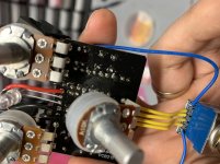
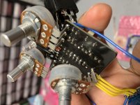
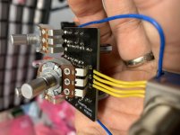
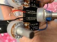
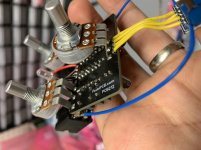
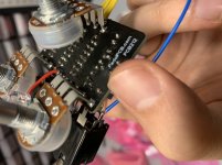
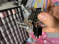
I’ve attached some pictures of the board from the top side. I know it could use an IPA wipe down but to be honest that’s never resulted in an issue like this for me and I’ve done ones that looked worse.

mill have to wait til tomorrow to get a picture of the underside (I stupidly didn’t take a picture when I pulled it out to reflow joints). Underside looks better than top though since that’s the side I soldered from.

anyways I’m just hoping these ic voltages are enlightening. TIA
 

Attachments

  • CEFBDF3C-B610-46B6-9D00-D56AAC5DEA0D.jpeg
    CEFBDF3C-B610-46B6-9D00-D56AAC5DEA0D.jpeg
    370.9 KB · Views: 22
  • 1168C02D-A1A4-4E15-99C1-3BDFD2FB4177.jpeg
    1168C02D-A1A4-4E15-99C1-3BDFD2FB4177.jpeg
    318.9 KB · Views: 22
  • 77BA52DB-C6BE-4C3C-9B98-F9A339208039.jpeg
    77BA52DB-C6BE-4C3C-9B98-F9A339208039.jpeg
    382.3 KB · Views: 23
What's the voltages on the empty IC1 socket

I'd check VREF points on the schematic pins 1 and 7 outputs seem about right with 8.2v going in, 3, 5 and 6 look way off

You should have half the power supply at the junction of R101 and 102 the voltage divider and at all your VREF points less voltage drops through resistors etc
 
Last edited:
What's the voltages on the empty IC1 socket

I'd check VREF points on the schematic pins 1 and 7 outputs seem about right with 8.2v going in, 3, 5 and 6 look way off

You should have half the power supply at the junction of R101 and 102 the voltage divider and at all your VREF points less voltage drops through resistors etc
Empty socket

1: 0
2: 0
3: 0
4: 0
5: 0
6: .18
7: .1
8: 8.2
 
8.9 coming into D100 and 8.2 coming out

Also 8.2 going into R101 but only .47 coming out

.47 at R2 R3 and R12. Didn’t check the two other Vref spots because the caps are under the board but it would appear the issue is the voltage divider
 
Last edited:
Both R101 and R102 are reading 4.2k. The other Mach 1 thread suggests there is probably something being grounded.

No dc voltage from input tip to ground
 
Your problem from what you're saying starts at R101 double check the solder joints R101, 102 and C101

It could be any of those components shorting or bridged

I wouldn't worry about resistance readings you won't get accurate readings in circuit most of the time
 
Your problem from what you're saying starts at R101 double check the solder joints R101, 102 and C101

It could be any of those components shorting or bridged

I wouldn't worry about resistance readings you won't get accurate readings in circuit most of the time
Ok thanks I’ll take a look this afternoon
 
Ok update I reflowed those resistors and cap. One of the resistors did have a big blob of solder sitting on top of the joint so that was probably it. The voltage still isn’t right but when I engage the pedal I get sound. It sounds pretty good except now it appears the volume and drove pots need to be almost fully clockwise for me to get volume. Tone control appears to work just fine.

should I reflow the pot lugs?
 
Recheck IC1 with empty socket. Mainly pins 3, 6 and 8. With ic removed these should have voltage on them. Pins 3 and 6 should be around 4Vdc and pin 8 should be >8Vdc. Pin 7 will have voltage also if pin 6 has it.
 
OK those didn't change from the initial readings earlier. With out the 4 to 5 volts on pins 3 and 6, this circuit will not work right. I'm assuming you still have .47 between R101 and R102 also. You also stated you have 4.7K across R102, it should be 5.6K. You may have a leaky cap. The most likely culprit would be C101, hard to check it in the circuit, or there is a partial short somewhere, maybe on backside of board. Its also possible to create a short in the residual solder flux, it traps small particles of solder in it and can create a short, for good measure try and clean it up with alcohol and toothbrush. From what I can see on the pics, it doesn't appear that you have cold solder joints, I can see where the solder flowed through from the back side, which is good.

If your careful you can lift the board out of the enclosure with out de-soldering power connections. Give it a good cleaning front and back and check backside of board for possible short. With board out of enclosure check voltages on IC socket with out IC. If there is nothing obviously shorted and voltage of Vref is still low then double check R101 and R102 solder joints from the back, if good then you need to check the caps. C1 and C2 can't be ruled out per se`, but highly unlikely as Vref would be a little higher. C101 is a pain to check, you would have to remove it from the circuit. Since its a power filtering cap, the circuit will work without it, there may be a lot more noise is all. So if you remove it, check the same voltages on the IC socket without the socket. If they are still low without C101, then thats not it and will have to regroup and form new plan of attack. Which is a normal thing in electronics trouble shooting, go after the most probable thing, then weed your way down.
 
. ... normal thing in electronics trouble shooting, go after the most probable thing, then weed your way down.

Ok great and thank you for the help man. I’m going to get the board out tonight and clean it with some ipa and try these other suggestions. I’ll probably just desolder the power connection so it’s easier to clean. Getting pretty good at using solder wick now.
 
Ok here are some pics. I was having a hard time getting detailed close up but I think I see one joint that looks pretty bad. R3 I believe. Also do you think R101 and R102 look like too much solder?
 

Attachments

  • 6FE2C17C-1C11-4CA3-B187-CB1B549757B9.jpeg
    6FE2C17C-1C11-4CA3-B187-CB1B549757B9.jpeg
    270.3 KB · Views: 17
  • F3F05C49-DB7B-450E-9919-B11A85590905.jpeg
    F3F05C49-DB7B-450E-9919-B11A85590905.jpeg
    264.9 KB · Views: 17
  • EC06350C-5271-4926-BEEA-11378B0B0E21.jpeg
    EC06350C-5271-4926-BEEA-11378B0B0E21.jpeg
    323.8 KB · Views: 16
  • 1AB0BAA3-73A0-4426-A612-FF6E2521225C.jpeg
    1AB0BAA3-73A0-4426-A612-FF6E2521225C.jpeg
    215.3 KB · Views: 16
  • B0162E4A-1FAC-4228-91EB-53E4801166D0.jpeg
    B0162E4A-1FAC-4228-91EB-53E4801166D0.jpeg
    259 KB · Views: 15
  • 1B2C0E40-CAD2-46D0-BA2C-C4B543ECB409.jpeg
    1B2C0E40-CAD2-46D0-BA2C-C4B543ECB409.jpeg
    246.3 KB · Views: 13
  • B33CECA3-467C-4CC0-9B00-1B935FD7F121.jpeg
    B33CECA3-467C-4CC0-9B00-1B935FD7F121.jpeg
    250.3 KB · Views: 16
I know angle of pics can be deceiving but I’ve checked and there are no obvious components shorted to other points. Def not ruling out a short due to flux residue
 
OK the R3 connection is questionable, reflow that. Also the R2 connection on the inside of the board, it has a ball shape to it in pics, this is a sign a joint could be cold. Both R2 and R3 would keep voltage from pins 3 and 6. Add a little solder to R3 and reflow R2, with as much solder as there is on R2, you shouldn't have to add any solder to it. Just touch the iron to it until it melts and flows nicely.
 
Back
Top