SOLVED Mach 1 Overdrive power issues

caiofilipini

Well-known member
Hi there,

This is my first post, and first PedalPCB build! It's my second ever build, the first one being a kit from Aion, which made a couple of things easier, especially wiring. I don't have much experience, so soldering skills are not great either, but the Aion build worked just fine.

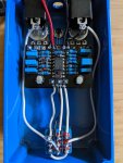
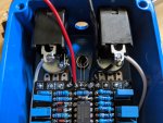
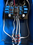
This time around, I'm building the Mach 1 Overdrive (Greer Lightspeed). I've wired everything last night, and bypass signal works fine, but when the circuit is engaged, the LED doesn't light up and there's no audio coming out. A few notes:

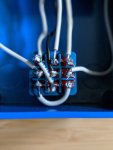
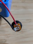
1) I measured the lugs on the DC jack with a multimeter and the positive lug gets ~9.38V from the power supply. I also measured the same voltage on the other end of the wire before connecting it to the board. After wiring it to the board, I get ~0.15V on the wire.
2) I accidentally bought the wrong sized DC jack, so I only wired it up so I could test the circuit before the correct jacks are delivered.

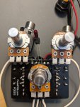
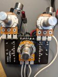
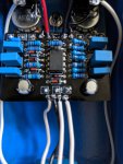
Here are some pictures of the build:

I'm sure there's something obviously wrong, but without the experience, I can't pinpoint it myself.
Any thoughts?

Appreciate the help, folks!
 

Attachments

  • 00100dPORTRAIT_00100_BURST20200609103815962_COVER.jpg
    00100dPORTRAIT_00100_BURST20200609103815962_COVER.jpg
    705.2 KB · Views: 24
  • 00100dPORTRAIT_00100_BURST20200609103945245_COVER.jpg
    00100dPORTRAIT_00100_BURST20200609103945245_COVER.jpg
    679.6 KB · Views: 21
  • MVIMG_20200609_103744.jpg
    MVIMG_20200609_103744.jpg
    761.6 KB · Views: 22
  • MVIMG_20200609_103853.jpg
    MVIMG_20200609_103853.jpg
    775.9 KB · Views: 22
  • MVIMG_20200609_104014.jpg
    MVIMG_20200609_104014.jpg
    741.4 KB · Views: 25
  • MVIMG_20200609_104031.jpg
    MVIMG_20200609_104031.jpg
    759.9 KB · Views: 24
Your photography skills are very good. Solder skills needs some work. Your iron is not hot enough and you're using way too much solder. It sounds like you have a short on the board between Vcc and ground. I'll bet D100 gets hot when you power up the board. With power off, measure the resistance from pin 8 to pin 4 on IC1. Put the red lead on pin 8. Is there a dust cover on the TONE pot?
 
Your photography skills are very good. Solder skills needs some work. Your iron is not hot enough and you're using way too much solder. It sounds like you have a short on the board between Vcc and ground. I'll bet D100 gets hot when you power up the board. With power off, measure the resistance from pin 8 to pin 4 on IC1. Put the red lead on pin 8. Is there a dust cover on the TONE pot?

Thank you, @Chuck D. Bones! Yeah, definitely need to step up my soldering game, which is one of the reasons why I'm building these! I'll use a hotter setting from now on. I've been using a Weller WLC100 iron set at about 3 (from 1-5).

I just measured 674 ohms from pin 8 to pin 4. I'm not really sure whether or not that's in the ball park.
Also, there is no dust cover on the tone pot, I don't have any covers around. Should it try some electrical tape to maybe rule that out as the source of a short?
 
That's a decent reading. You definitely need some insulation between the pot body & the board. Not electrical tape, it's too soft and a sharp lead will poke right thru. Use a thin piece of cardboard, like from a cereal box, or a business card. Did D100 get hot? Does the power plug fit the jack snugly?
 
@Chuck D. Bones How hot? I touched it a few times with the power on and couldn't feel much heat. The power plug fits pretty snugly, yeah.

I removed everything from the enclosure, then re-soldered some of the wiring from the power jack to the PCB and I can at least measure the same ~9V on the wire coming into the PCB now. But still no sound. I also verified the body of the tone pot is not touching any of the leads underneath it (and I placed a piece of cardboard there too, as you suggested).

Any obvious things I could check next?

Thanks again, much appreciated!
 
With power on, measure the voltage on the anode of D100 to ground. Take some pix of the solder side of the board. You probably have a cold solder joint where the power leads comes onto the board. Where did you get your wire? I bought some solid wire from Tayda and it's difficult to get solder to wick up on it. I have to pre-tin every wire or else I get a shitty connection. I won't be buying wire from them any more.
 

Attachments

  • MVIMG_20200609_161243.jpg
    MVIMG_20200609_161243.jpg
    823.3 KB · Views: 14
  • MVIMG_20200609_161311.jpg
    MVIMG_20200609_161311.jpg
    850.2 KB · Views: 13
You need to clean up the solder joints, waaaaaay too much solder, and clean the flux residue off of the board with IPA. I marked the two worst offenders, but you need to inspect every joint and fix all of the bad ones. A good solder joint will be shiny and more-or-less conical in shape. If it looks like a big blob, there is too much solder and it may not be adhering to the pad. If you jiggle or twist the wire and it moves in the pad, you need to redo the joint. The area I marked as possible short might be fine, but since I have only a 2D view, it looks like the two joints are touching. There may be more bad shit under the TONE pot; you'll have to carefully bend it out of the way and inspect. I inspect my boards under magnification before installing pots, switches, or anything else that will obscure the view. I can't tell from the pix if the LED is installed facing the right direction. The short lead or flat side should go to the square pad.

caiofilipini's Mach 1.jpg
 
@Chuck D. Bones I'll double check all of those joints tonight, thanks!

The LED is a funny one, I can't really tell which lead is which, they're basically the same. Would it prevent the circuit from working altogether in case they're inverted, or it simply wouldn't light up? I'll post a picture of a loose LED later, but they're exactly these ones:

 
if your LED is not lighting up when it should use you multimeter to see if there is power going to the leads. if so, touch another led leads to those and see if that LED lights up (reversing them if they do not light up the first way). If the new LED lights you either have your LED soldered in backwards or it is bad.
 
if your LED is not lighting up when it should use you multimeter to see if there is power going to the leads. if so, touch another led leads to those and see if that LED lights up (reversing them if they do not light up the first way). If the new LED lights you either have your LED soldered in backwards or it is bad.

I'm thinking it doesn't need a 4.7K series resistor. But let's get the sound working first.
 
Okay, quick update after cleaning up most of that mess: we have sound!

Mach 1 Lightspeed Clone Clip 01

Still a couple of things to cleanup and fix, including the LED (I'll just replace that bulb with a proper LED), the correct-sized DC jack and knobs that I'm waiting to get delivered. But it's working, and sounds kind of like I expected it to sound. What do you all think?

Again, thank you so much for all your help, @Chuck D. Bones and others who chimed in as well, much, much appreciated!
 
Last edited:
Back
Top