Hi All!
So some of you saw my first ever post and first PedalPbc build (VHS) in the build section the other day. This was my second successful build; my first build was with a board purchased from a competitor (who shall remain unnamed). Even though the build went well, I had some questions about the finished product; and so I did what most people would: went to their forum with my questions. Well, either their forum is dead or nobody wishes to help me, so since I received such a warm welcome from you guys the other day, I feel like I bring a few general beginner questions here and maybe get some help.
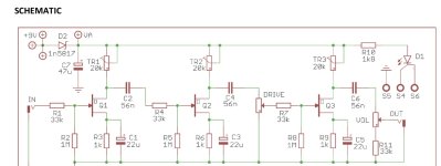
So this competitor’s circuit is meant to emulate
3 old fender amps of yore and simply has volume and drive controls. The drive packs a heck of a punch, as the description in the instructions state. But the description also says that it ranges “from a clean boost to overdrive”, however the thing is there’s nothing clean about even the lowest drive or volume settings on the one I built: it ranges from light dirt to pure filthy breakup. Don’t get me wrong, it’s pretty, but I wish it would start out as a clean boost as stated, and I’m wondering why it doesn’t. So my questions are 3:
1. The build contains 3 trim pots. Could how I set my trimmers have an affect on this issue? I know I installed them correctly, but I had no idea what to do regarding setting them afterword. I have never worked with trimmers before, so I just fooled around with the settings until I found the one I thought sounded the best.
2. Could switching transistors affect how clean/dirty it sounds? I used the 2N547 listed in the build instructions, but the instructions also suggested possibly experimenting with a J113, MPF102, or J201. How would switching the transistor up affect the sound?
3. And finally, could have I have done something wrong with the build to cause this?
forgive the long post and possible dumb questions. Keep in mind I’m just a beginner") . I’m really disappointed I was left in the dark in this competitor’s forum. I’m not sure if I’ll shop there again. PedalPcb and this forum have really impressed me thus far, so I think I might stick around.
. I’m really disappointed I was left in the dark in this competitor’s forum. I’m not sure if I’ll shop there again. PedalPcb and this forum have really impressed me thus far, so I think I might stick around.
Thanks in advance for your time and help! And if I should have posted these questions elsewhere in the forum, please kindly let me know
So some of you saw my first ever post and first PedalPbc build (VHS) in the build section the other day. This was my second successful build; my first build was with a board purchased from a competitor (who shall remain unnamed). Even though the build went well, I had some questions about the finished product; and so I did what most people would: went to their forum with my questions. Well, either their forum is dead or nobody wishes to help me, so since I received such a warm welcome from you guys the other day, I feel like I bring a few general beginner questions here and maybe get some help.
So this competitor’s circuit is meant to emulate
3 old fender amps of yore and simply has volume and drive controls. The drive packs a heck of a punch, as the description in the instructions state. But the description also says that it ranges “from a clean boost to overdrive”, however the thing is there’s nothing clean about even the lowest drive or volume settings on the one I built: it ranges from light dirt to pure filthy breakup. Don’t get me wrong, it’s pretty, but I wish it would start out as a clean boost as stated, and I’m wondering why it doesn’t. So my questions are 3:
1. The build contains 3 trim pots. Could how I set my trimmers have an affect on this issue? I know I installed them correctly, but I had no idea what to do regarding setting them afterword. I have never worked with trimmers before, so I just fooled around with the settings until I found the one I thought sounded the best.
2. Could switching transistors affect how clean/dirty it sounds? I used the 2N547 listed in the build instructions, but the instructions also suggested possibly experimenting with a J113, MPF102, or J201. How would switching the transistor up affect the sound?
3. And finally, could have I have done something wrong with the build to cause this?
forgive the long post and possible dumb questions. Keep in mind I’m just a beginner
. I’m really disappointed I was left in the dark in this competitor’s forum. I’m not sure if I’ll shop there again. PedalPcb and this forum have really impressed me thus far, so I think I might stick around. Thanks in advance for your time and help! And if I should have posted these questions elsewhere in the forum, please kindly let me know