No drill template, like Moonn, What do you do?

Zanshin

Well-known member
I'm about to start some new builds, mostly from Moonn, and I realized Moonn provides no drill templates.

My process is I make the art with drill marks using a drill template as a guide. Apply the art to the enclosure. Auto punch the marks, and then Rotabroach with the drill press. As long as my decal placement and auto punches are accurate it's as good as I can imagine doing it by hand can get.

My first thought was pen through the pot pin2 PCB through-hole onto some paper to get some measurements for my art. But that might be error prone haha. On my drive home I thought I'd try my scanner.
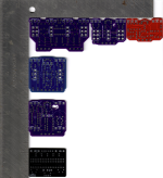
Screenshot 2024-08-22 205954.png

PPCB on the bottom for reference (well and it's in the same build batch as the others). I printed my scan and it seems to match up with the PCB as perfect as far as my old eyes can judge. Plus the ruler is a reference.

Any better methods out there before I jump?
 
Last edited:
I found designing drill templates way easier after I picked up a digital caliper. I didn’t even spend $10 on it.

For moonn pcbs, I start with the face of the enclosure drawn on a piece of paper.

I measure where the middle is vertically and horizontally. And mark it. The two lines should cross smack in the center.

Then on the back of the pcb, I measure from the pin 2 hole to the cross in the center of the circle where the potentimer will end up.

After I decide how high up the top pots will go, I use that measurement to trace the funky shape of the pcb (keep in mind which side is the correct one), so I don’t end up with things like the footswitch colliding with the pcb.
 
Keeping in mind that the pot shaft center is 16.5mm from the middle hole, lots of caliper measurements and double checking. I usually just draw it all it in Illustrator. It has turned out that many Moonn boards use the same spacing as PPCB--but not always.

Scanning is a great idea, because Moonn's build docs just have a snapshot of the board, from a slight angle.
 
I've always measured the PCB's pot and switch points, and then transferred those measurements directly to the enclosure — no templates, ever.
Wait, I lied. I do use the template cover that Robert sells, but haven't ever used a printed-paper template. If it's not a PPCB board I measure everything myself and mark it out on the enclosure — pencil on bare-metal, or painter's-tape if the enclosure is already painted.

After painstakingly measuring and remeasuring and then checking those measurements and precisely marking the enclosure with great precision, delineating perfect places for pots and switches all pin-point pencilled in (I have photographic proof, Ginger's mole could only aspire to being such a beauty mark as my enclosure's punch-points)...

902e4624c698fa1c120d304a9e22e52b.jpg


So far so great!...
02fa4f5c-0211-4d3a-a8f1-2ec58287f69a-jpeg.25976

and then...

I still manage to mangle the machining and badly botch the bore-holes. 😫


Wait, he said...


Mole! MOHHHHLEY MOLEY MOLEY MOLEY ! ! !

He said mole.

-6EXOk.gif

Mole !


☀︎
.
 
Keeping in mind that the pot shaft center is 16.5mm from the middle hole, lots of caliper measurements and double checking. I usually just draw it all it in Illustrator. It has turned out that many Moonn boards use the same spacing as PPCB--but not always.

Scanning is a great idea, because Moonn's build docs just have a snapshot of the board, from a slight angle.
I'll say this:

That 16.5mm number is very, *very* fudgeable. Pot leads bend. Precision isn't so important on the y axis.

Digital calipers are a godsend. Round to the nearest half a millimeter or so. A metric combination square helps here. Ditto to a sheet metal scribe.

I don't typically use drill templates: honestly, I have better results when I measure directly on the board and use that to do a quick mockup of hole placement in inkscape.

Granted, I let my CNC router take care of all the hole cutting.
 
Back
Top