SOLVED No sound from Caesar Chorus

bhcarpenter

Well-known member
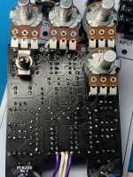
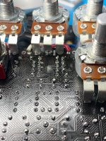
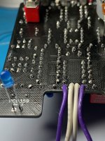
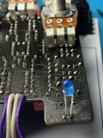
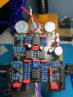
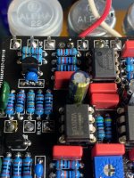
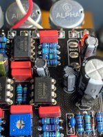
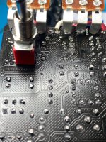
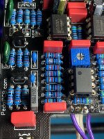
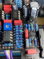
This might be the first pedal that I’ve gotten no output from (after remembering to pop the ICs into their sockets). I cleaned with ISO and did a visual inspection, but I’m stumped. I guess I should try an audio probe next, but there’s no schematic posted. Hoping that someone notices something obvious that I just missed.

The rate indicator LED seems to be throbbing correctly if that’s any help.
 

Attachments

  • 0D35D221-6897-4927-8F76-90DE968230A7.jpeg
    0D35D221-6897-4927-8F76-90DE968230A7.jpeg
    749.2 KB · Views: 23
  • B4E1C215-E119-468D-B628-461C7D880321.jpeg
    B4E1C215-E119-468D-B628-461C7D880321.jpeg
    632.2 KB · Views: 18
  • 440FC313-DF52-4AC8-B201-264FD1BBBB1E.jpeg
    440FC313-DF52-4AC8-B201-264FD1BBBB1E.jpeg
    509.8 KB · Views: 16
  • C1DCF493-2BE5-4EAB-9301-56B45677165A.jpeg
    C1DCF493-2BE5-4EAB-9301-56B45677165A.jpeg
    525.3 KB · Views: 21
  • D46AB6C7-2742-456A-A200-2EA92B472196.jpeg
    D46AB6C7-2742-456A-A200-2EA92B472196.jpeg
    501.9 KB · Views: 28
  • A75146F8-85A1-44F4-8BD9-DFE1BF92F92D.jpeg
    A75146F8-85A1-44F4-8BD9-DFE1BF92F92D.jpeg
    471.8 KB · Views: 29
  • CDF3249E-A648-46F7-AB7D-EFE319A7EEA1.jpeg
    CDF3249E-A648-46F7-AB7D-EFE319A7EEA1.jpeg
    487.8 KB · Views: 23
  • 2F4BCEE8-FB2D-4C5A-933D-E8E84B3A1581.jpeg
    2F4BCEE8-FB2D-4C5A-933D-E8E84B3A1581.jpeg
    669.9 KB · Views: 23
  • D5C323BC-841E-4F3A-BBEF-9B1286E36993.jpeg
    D5C323BC-841E-4F3A-BBEF-9B1286E36993.jpeg
    563.7 KB · Views: 23
  • 14C8B483-A468-481F-9030-8D22D5D9F0FE.jpeg
    14C8B483-A468-481F-9030-8D22D5D9F0FE.jpeg
    593.1 KB · Views: 24
your tl022 looks like it has some weird discoloration on the surface... from one angle it looks like a crack. maybe try swapping it out for an op-amp you know works... i used a tl072 for my caesar and it worked fine.
 
check your voltages on the IC pins and also confirm you have a ground connection on them. even without a schematic you can determine if audio is going in and out of the op amps and BBD which can help isolate the circuit.
 
That was a good spot @vladimirsky, but sadly a new opamp didn’t help.

@zgrav when you say to check the voltages on the IC pins, you mean just measure voltage from ground to each pin? So I’d power it up, but not plug anything into input, and just measure volts with a DMM? Sorry for the noob question.
 
You have the right idea -- put one of your probes to circuit ground, power the circuit board and measure all of the pins on the ICs to see where you are getting power and what the voltage is. you know some power is reaching at least some components because your rate LED is flashing. while you are doing that, you may be able to see if you have a varying voltage reaching one of your op amps that is in synch with your rate pot.

I would turn off the power and check each IC pin to see where you have continuity to ground.

I did not try to verify your part values but the board looks clean and I did not see any shorts or bad connections.

are you sure that your pot beside the switch is not in contact with it?

do you have an audio probe? that is another way to start checking whether any audio is reaching your op amps and BBD. you can look at the parts near the wires that go in and out of the board and do some spot checking to find out where your audio is going.
 
Double-checked that pot wasn’t touching the switch. Here are the pin voltages. All of the 0v pins have ground connectivity.

IC1 (TL022)
—————
1. Around 0.5v - 8.5v *
2. Around 4.5v. Didn’t stabilize
3. Around 2.5v - 6.5v *
4. 0v
5. Around 4.5. Didn’t stabilize
6. 3.0v
7. Around 2.5v - 6.5v *
8. 9.1v


* Seems to be oscillating in time with the rate LED

IC2 (RC4558)
——————
1. 8.8v
2. 8.4v
3. 8.8v
4. 0v
5. 8.9v
6. 8.9v
7. 8.6v
8. 9.2v

IC3 (V3207)
—————
1. 0v
2. 4.5v
3. 7.9v
4. 8.5v
5. 9.1v
6. 4.5v
7. 7.9v
8. 8.9v

IC4 (V3102)
—————
1. 9.1v
2. 4.5v
3. 0v
4. 4.5v
5. 0.2v
6. 8.9v
7. Around 2.9v - 3.3v *
8. 8.5v

* Seems to be oscillating in time with the rate LED
 
Ok, with the audio probe I could tell that there was signal going into pin 2 of IC 2, but only noise coming out of pin 1. Hrm... D’oh! All I needed to do was adjust the trimmer. 🤦‍♂️
Glad you sorted it out, such a nice effect.
Better to feel a bit dumb than having to desolder a bunch of things! I know I had similar scenarii happen to me.
 
Back
Top