No sound when Cujo Fuzz engaged

allsmoke

Well-known member
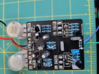
Is there anything immediately outstanding as to why I'm not getting anything when active? The only thing I thought was maybe a pot and switch touching, but I put a piece of electrical tape in to stop them.
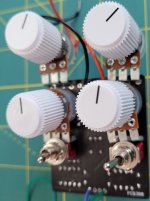
Sound in bypass, but nothing when engaged. I'll post a pic of the top in the reply as it's telling me too large to post both on this.

Any advice would be much appreciated.
Thank you,
 

Attachments

  • Cujo bottom.jpg
    Cujo bottom.jpg
    1.9 MB · Views: 14
  • Like
Reactions: fig
Can you post picture of the whole assembly ? Top of board, input/output jacks and footswitch...

Most common problem for by-pass working and not engaged, that I have seen, is reversed input/output jack wiring or at the switch. We need a view where we can trace the wiring first... then you'll need to chase that ghost with a audio probe to see where the sound stop in the circuit. You should also double check all your values to be sure you didn't make a mistake....

I don't do that stage until I test the circuit on the Micro Proto Board so the jacks and footswitch are not part of the problem. So this is something within the circuit

Coda: The schematic calls for J202s, which I don't have, so I used 201s instead. I got them from Tayda, but tested them on my component tester beforehand.

Which tester? I’m not saying it’s definitely the issue, but when Jfets are involved in a non-functioning circuit, I always triple check.

Edit: looking over the schematic, I doubt the Jfets would be the issue. Unless they are especially out of spec, J201 tends to have a tighter spread than the J202. Reading the voltage off of the source would answer that question quickly.
 
Last edited:
We want to see the Drain voltage on Q1, Source voltage on Q4. Suhr (or the person who traced the circuit) has the FETs upside-down. Not to worry, they work fine that way. This thing has a 4.7K input impedance, which is extremely low and will load the pickups big-time. Apparently Suhr did this on purpose because their manual say Input Impedance 5K. Try driving this with another pedal. Check the voltage on Q3-C and above all, do a thorough visual inspection. We can only read three of the caps. Any parts subs, other than the FETs?
 
Which tester? I’m not saying it’s definitely the issue, but when Jfets are involved in a non-functioning circuit, I always triple check.

Edit: looking over the schematic, I doubt the Jfets would be the issue. Unless they are especially out of spec, J201 tends to have a tighter spread than the J202. Reading the voltage off of the source would answer that question quickly.

Using this. Here's the values it's reading
 

Attachments

  • 20220411_115537.jpg
    20220411_115537.jpg
    1.2 MB · Views: 5
  • 20220411_115602.jpg
    20220411_115602.jpg
    1.5 MB · Views: 5
We want to see the Drain voltage on Q1, Source voltage on Q4. Suhr (or the person who traced the circuit) has the FETs upside-down. Not to worry, they work fine that way. This thing has a 4.7K input impedance, which is extremely low and will load the pickups big-time. Apparently Suhr did this on purpose because their manual say Input Impedance 5K. Try driving this with another pedal. Check the voltage on Q3-C and above all, do a thorough visual inspection. We can only read three of the caps. Any parts subs, other than the FETs?
No subs apart from the FETs.
I'm getting 0.7 v reading with the multimeter, but I'll be honest, I'm not 100% sure if I'm doing it correctly.
 
We want to see the Drain voltage on Q1, Source voltage on Q4. Suhr (or the person who traced the circuit) has the FETs upside-down. Not to worry, they work fine that way. This thing has a 4.7K input impedance, which is extremely low and will load the pickups big-time. Apparently Suhr did this on purpose because their manual say Input Impedance 5K. Try driving this with another pedal. Check the voltage on Q3-C and above all, do a thorough visual inspection. We can only read three of the caps. Any parts subs, other than the FETs?

Getting 5v on the drain on Q1, 6.6v on the source on Q4

And thank you for the guidance.
 
  • Like
Reactions: fig
Those are decent readings. Q4-S could be lower for more headroom, but the pedal will work with those values. If you want, you can try different JFETs for Q4 and see if you can get around 5V.

How about Q3-C, did you measure that one?
 
I'm really curious about something and this is a learning opportunity for me and not a critic. You focus directly on the FET as a single point of failure for the sound not making it through, but there's a multitude of other reasons for the sound not making it. I would have expected a trace with an audio probe first to find where is the signal stopping.

Any reason in this particular case not to go to audio probe straight up ?
 
It's more objective to measure the DC bias points with a DMM then to poke around with an audio probe.

I like to do it in this order:
Visual inspection
DC bias points
Probing with scope or audio probe

The deal with FETs is it's easy for people to get the bias wrong. The pro builders screen the parts before putting them on the board. DIYer's for the most part don't know what the screening criteria for a particular circuit is, so they have no way to screen the parts.
Interesting, I always thought, wrong bias equals bad sound, not wrong bias equals no sound ! So my natural reflex was find out where the signal dies first and focus on that area....
 
OK, so I'm going to build an audio probe to test the circuit next because everything seems to be ok measurement wise. I just want to make sure I have this correct

Mono jack - shield lug goes to ground wire/alligator clip - tip lug goes to live wire/220nf cap/probe tip.

Then I plug the guitar into the micro test board as normal, and the amp into the audio probe mono jack. Play some music back on my looper through it, and test the various components along the circuit to see if there's a fail somewhere.

Does that seem about right?
 
Back
Top