Pumbaa Distortion - No sound when engaged

My turn to ask for some help. I'm still fairly new to building pedals, and had about 10 pedals that worked great, but suddenly I've been on a bad streak, and this is my 2nd pedal that's got an issue.

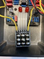
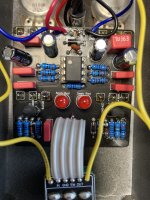
Building the Pumbaa Distortion, and I get full sound when bypassed. When engaged, the sound is so low (even when volume and gain are cranked) as to be imperceptible. When playing, I see that both LED's light, then slowly fade with the sound.

Any help would be appreciated!
 

Attachments

  • IMG_6206.jpg
    IMG_6206.jpg
    512.9 KB · Views: 22
  • IMG_6207.jpg
    IMG_6207.jpg
    560 KB · Views: 21
I’ve gone back over and reflowed my joints, and still getting only the tiniest of buzzy distortion.

I replaced the LED with a more standard 5mm LED (previously had installed a pre-wired LED from LMS, which was slightly edging up against the top of the board.

No obvious damage to any of the caps or wires.

I did buy the IC from Tayda, so I’m planning on buying a different one, as I’ve heard that Tayda can be shaky at times.

I really don’t know how to troubleshoot with a MM (which I own) or an audio probe (which I don’t own), so any advice on why I’m not getting sound would be appreciated.

Thanks!
Here’s my troubleshooting workflow:

1. Close visual inspection - component values, polarity, pinouts; solder joints; wire breaks, etc etc etc.
2. If that’s all good, I check voltages at the protection diode, transistors and ICs.
3. If that’s all good, I audio probe - if you run a search on the forum, you’ll find more than you ever wanted to know about how to make one (it’s easy and cheap) and use it.

Friendly advice - Don’t start taking components out or switching them around unless you verify they’re a problem. Tayda is a good source for parts.
 
can you post a clean pic of the other side of the board?

take the time to read about using an audio probe and spend a few minutes making one. that will let you isolate a problem area in the circuit for further inspection.
 
Here’s my troubleshooting workflow:

1. Close visual inspection - component values, polarity, pinouts; solder joints; wire breaks, etc etc etc.
2. If that’s all good, I check voltages at the protection diode, transistors and ICs.
3. If that’s all good, I audio probe - if you run a search on the forum, you’ll find more than you ever wanted to know about how to make one (it’s easy and cheap) and use it.

Friendly advice - Don’t start taking components out or switching them around unless you verify they’re a problem. Tayda is a good source for parts.
Thanks for the advice. I’ve been fortunate enough so far that most of my builds have been successful, so I’ve never taken the time to learn the “proper basics” of troubleshooting (ie. reading schematics, understanding flow through the circuit, testing voltage). So I will take this as an opportunity to learn the fundamentals, and hopefully fix a pedal along the way.

Thanks!
Do you have the correct OpAmp as asked above?
 
Can you give the voltages on the OpAmp
1........8
2........7
3........6
4........5
That will be my first step…once I learn how to do that! 😀

I’ve got a few “how to troubleshoot diy pedals” videos saved on my YouTube watchlist to learn how to do this type of troubleshooting. I’ve got a multimeter, I just have never learned how to test continuity and voltages yet.
 
That will be my first step…once I learn how to do that! 😀

I’ve got a few “how to troubleshoot diy pedals” videos saved on my YouTube watchlist to learn how to do this type of troubleshooting. I’ve got a multimeter, I just have never learned how to test continuity and voltages yet.
Just set your DMM to DC Volts, Red Probe on each pin, Black probe to Ground on PCB.
1........8
2........7
3........6
4........5
 
That will be my first step…once I learn how to do that! 😀

I’ve got a few “how to troubleshoot diy pedals” videos saved on my YouTube watchlist to learn how to do this type of troubleshooting. I’ve got a multimeter, I just have never learned how to test continuity and voltages yet.
Set your DMM to 20V DC (or whatever amount is the next greater than the 9v you're powering the circuit). Black lead to ground. Red lead to each pin of the opamp. The numbering of the opamp pins is "standardized" by going counterclockwise.
 
Set your DMM to 20V DC (or whatever amount is the next greater than the 9v you're powering the circuit). Black lead to ground. Red lead to each pin of the opamp. The numbering of the opamp pins is "standardized" by going counterclockwise.
I’m honestly not entirely confident that I’m doing it correctly, but using my Klein MM400 multimeter, set to “V” DC on the Auto setting.

So, here’s what I think I’m getting:

1 = -0.7
2 = 0
3 = -0.8
4 = -0.9
5 = -.149
6 = -.09
7 = -.057
8 = 0

Not terribly confident that that is correct though?
 
Last edited:
Yes, I plugged it in to a 9v supply.

As this is the first time I’ve done this, there’s a chance I’m doing it incorrectly.

I’ve got the black lead on ground, and using the red lead to touch each pin of the IC.
To confirm your DMM is set correct, Push the Black probe into the end of the centre hole of your Power supply jack that your plugging into the pedal and put the red probe on the side of the plug, you should be getting around DC 9.2 volts
 
You should be getting around that voltage on pin 7.
If not, you have an issue with a bad solder joint or debris on your solder side of the board.
It has to been clean of any flux or stray solder bits & you can look for solder bridges!!!
 
Back
Top