SOLVED Nuffin’ from my Muffin

scheffehcs

Well-known member
Hello, just finished a Green Russian Muffin Fuzz that doesn’t work! I’m still a noob and I’ve been lucky that my last 10 or so pedals have worked without issue, so I don’t have a lot of practice debugging. Bypass works, no sound when engaged. If anyone can see an issue in these pics or can help me to start debugging, I’d be much obliged.
 

Attachments

  • 79E6E332-CFAF-48A1-A28C-A159147EE7D0.jpeg
    79E6E332-CFAF-48A1-A28C-A159147EE7D0.jpeg
    311.3 KB · Views: 49
  • 650DE863-5760-4618-AD27-F83CE07E8BF9.jpeg
    650DE863-5760-4618-AD27-F83CE07E8BF9.jpeg
    329.3 KB · Views: 48
  • 99C02C0A-9308-4D59-9887-FE192D4A2040.jpeg
    99C02C0A-9308-4D59-9887-FE192D4A2040.jpeg
    321.7 KB · Views: 49
I think you need to clean up all of the solder joints. Most of them have too much solder and it looks like the solder didn't wet properly on some of them. It's recommended to shorten the leads on the transistors so they sit above the sockets.
What is the transistor part number?
What kind of iron are you using?
Do you have a DMM?
 
Thanks for the response. I do have a DMM and a signal tester. I have the Hakko FX888D, I forget what tip I’m using. The transistors are 2N5088. I have a 3.3n cap socketed in c10 because I don’t have a 3.9n. Also have some resistor subs as well - 330r instead of 390r at R5, R11, and R16. And 2k2 instead of 2k at R22

Yeah, I did this one very quickly, not my best soldering. I don’t know if it’s the solder or iron tip I’ve been using but it kind of blobs up. Maybe just too much solder.

Here’s a basic question - do I want there to be solder covering the pads on both sides of the circuit board? When it doesn’t flow through and cover the pads on the populated side, I tend to add more to make that happen.

Anyway I’m ready to dig into it a bit when I get home tonight. Thanks!
 
When the iron is the right temp, the solder will form a conical fillet. Looks like your tip is too small or your iron is too cold. If there is solder sticking to the lead and pad all the way around the circumference on one side, and the hole is filled enough that you can't see thru it, then you have enough solder. You do not need a fillet on the other side.

Those parts subs are plenty close. Don't expect to hear a difference if you change them out.
 
I think you need to clean up all of the solder joints. Most of them have too much solder and it looks like the solder didn't wet properly on some of them. It's recommended to shorten the leads on the transistors so they sit above the sockets.
What is the transistor part number?
What kind of iron are you using?
Do you have a DMM?
Soldering definitely needs some work, what temp you setting that iron to?
 
Ok, just went through and sucked/reflowed a lot of the bad looking ones. Still no signal with pedal on. Just printed out the schematic and got my looper and signal tester ready. Gonna start testing.

Iron is at 655.
 
Don't reflow everything. Fix the bad or marginal solder joints. The board will only take so much heating before the traces & pads start lifting.

How about we measure some DC voltage first and see if the transistors are biasing properly?
I always start with the easy stuff first:
1. Visual Inspection
2. DC Bias
3. Signal trace

With power on and no signal, check the collector voltage of each transistor. They should all be between 4.0V and 5.5V. If not, then we know where to look for a bad part or bad workmanship.

If that's all good, then set VOLUME & SUSTAIN to max, TONE to noon. Power on, apply a test signal and check these places in order:
1. Input jack.
2. Q1 collector.
3. SUSTAIN pot pin 2.
4. Q2 collector.
5. Q3 collector.
6. TONE pot pin 2.
7. Q4 collector.
8. VOLUME pot pin 2.
9. Output jack.

Somewhere along the line the signal will drop out. The problem area will be between that last place you heard signal and first place you don't.
What he said
 
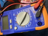
Ok so just to be sure - I have the multimeter set like this in the pic, then I connect the black lead to the negative terminal and the red lead to the collectors?

If so, here’s what I got:
Q1 - 8.76
Q2 - 8.76
Q3 - 8.02
Q4 - 5.18

Makes sense, I was messing with signal tester last night and Q4 was the transistor I found signal on.

So should I sub out these 3 transistors and see what happens?
 

Attachments

  • 7AD07666-B9AB-4DD4-B25D-347E3BDC73D1.jpeg
    7AD07666-B9AB-4DD4-B25D-347E3BDC73D1.jpeg
    109.8 KB · Views: 5
Oh boy. Took those measurements this morning before leaving for work. Q1E: 1.04, Q1B: 1.44. BUT I think I found the problem. I wired the power jack backwards. Will reverse tonight and see if that does it.
 
Oh boy. Took those measurements this morning before leaving for work. Q1E: 1.04, Q1B: 1.44. BUT I think I found the problem. I wired the power jack backwards. Will reverse tonight and see if that does it.
Unless the wires crisscross under the board looks right to me
 
Back
Top