Op Amp Static Troubleshooting

jdduffield

Active member
Hi,

I’m trying to figure out what type of noise this is so that I can try to fix it. Does anyone recognize what this is?

See video:

Maybe DC voltage getting on it, or maybe high frequency oscillation? I don’t know enough about what I’m listening for to diagnose.

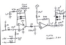
This is a design I came up with that works on a breadboard. See schematic attached. I’m trying to install it into a pedal.

I’ve ruled out a few things. The op amp is fine. I’ve tried swapping it and no luck.

It is a TL072. Using two non-inverting gain stages. First stage is fine (using pin 3, 2, and 1). Stage 2 has problems. Pin 5 sounds good. 6 sounds good. But 7, the output, sounds bad.

I’m getting 4.5v on vref, so my voltage divider is working.

Tried a few things, like adding a 47p cap across pin 6 and 7. Didn’t help. Seems all is well until the circuit gets to pin 7.

Btw - pin 8 has +9v as suggested by the schematic. Pin 4 is grounded.
 

Attachments

  • IMG_6198.jpeg
    IMG_6198.jpeg
    292.6 KB · Views: 17
Is the -9V on your schem actually ground? Or are you breaking Kirchhoff's second law?
I think it is technically considered a single power supply with +9V and 0V ground. (not exactly sure as I’m still in the learning stage) I’m using one power supply, 9V standard guitar pedal power plug with negative center. The rails are the red wire and the black wire from that.
 
Your second gain stage is 301x voltage gain? (300k/1k, +1) I'd be surprised and impressed to get more than 100x gain out of a single stage.
Are you sure that's the same as it was on a breadboard? I'd try changing the 300k resistor to ~30k.

I think it is technically considered a single power supply with +9V and 0V ground. (not exactly sure as I’m still in the learning stage) I’m using one power supply, 9V standard guitar pedal power plug with negative center. The rails are the red wire and the black wire from that.
Keep in mind GND is synonymous with 0V. You can have a positive voltage above that, or a negative voltage below that. In your schematic you used "-9V" to mean the power supply's negative lead. A better way to label would be "supply -" instead of "-9V." A true -9V would be adding a battery and connecting its positive lead to gnd. The negative lead would then be 9 volts below ground, or "-9V". It's all relative.
 
Last edited:
It's white noise and could be coming from any of the components or even from outside the pedal. Every component that conducts current generates thermal noise just from the electrons randomly crashing around. You have a shit-ton of gain there.

I would expect pin 7 to be much louder than pin 5, but in your video it is not. Recheck the feedback resistors, connections, etc. Why would you want 300x gain for the 2nd stage?

Best practice to minimize noise is to put most of the gain in the 1st stage and less in subsequent stages. The reasoning is that each stage magnifies the noise for previous stages. 5x gain on the 2nd stage should be plenty loud.

I personally do not like connecting anything to Vref that could be connected to GND. That 10nF cap on the 2nd stage for instance.

It would be easier for us to discuss the particulars of the schematic if you give each part a ref des, i.e. R1, C1 U1A, etc.

This looks like a TS with no TONE knob. Can you tell us what you want this pedal to do and why you designed it the way you did? That would make it easier for us to suggest solutions.
 
Also, if you want to try lowering the second gain stage's gain, you can temporarily alligator clip in (or tack solder) another resistor in parallel with the 300k feedback resistor. That way no desoldering :). I like chuck d bones suggestion of around 5x gain. Maybe try a 4.7k or 6.8k and see if the noise improves.
 
Are you sure that's the same as it was on a breadboard? I'd try changing the 300k resistor to ~30k.
I’m starting to think that the breadboard had something like a resistor leg on it somewhere that wasn’t making a connection. It sounded so different, and I remember also thinking it was odd to have 300x gain. I think I started with a 75k, then 100k, 200k, and landed at 300k. But maybe something else was loose.
 
Can you tell us what you want this pedal to do and why you designed it the way you did? That would make it easier for us to suggest solutions.
Well… I had picked up some unbranded vintage germanium diodes on eBay. They weren’t expensive, but looked pretty cool so I bought them.

I’d like it to have soft clipping and hard clipping balanced in such a way that showcases the sound of the diodes.
 

Attachments

  • IMG_6157.jpeg
    IMG_6157.jpeg
    218.6 KB · Views: 2
  • IMG_6158.jpeg
    IMG_6158.jpeg
    170.1 KB · Views: 2
Last edited:
I would try adding an R/C power filter first and foremost, small series resistor, 100R or thereabouts and a large electro cap, 22uF (increasing in size with smaller resistors) to ground between your 9V input and all the pedals power supply pins.

Then I'd start messing with the circuit itself.
 
Did you measure the leakage of the Germanium diodes? We can only use the very lowest leakage Germanium diodes as soft clippers because the leakage kills the gain. I'll be surprised if you get more than 10x gain in the 1st stage using the "average" Germanium diode.

Does anyone recognize those diodes? I've never seen anything like that before.
I measured the forward voltage but not sure about leakage. They measured around 0.27.
 
Back
Top