You are using an out of date browser. It may not display this or other websites correctly.
You should upgrade or use an alternative browser.
You should upgrade or use an alternative browser.
OPA4134 - what should I build?
- Thread starter ftumch
- Start date
Maybe an OD-1?
 aionfx.com
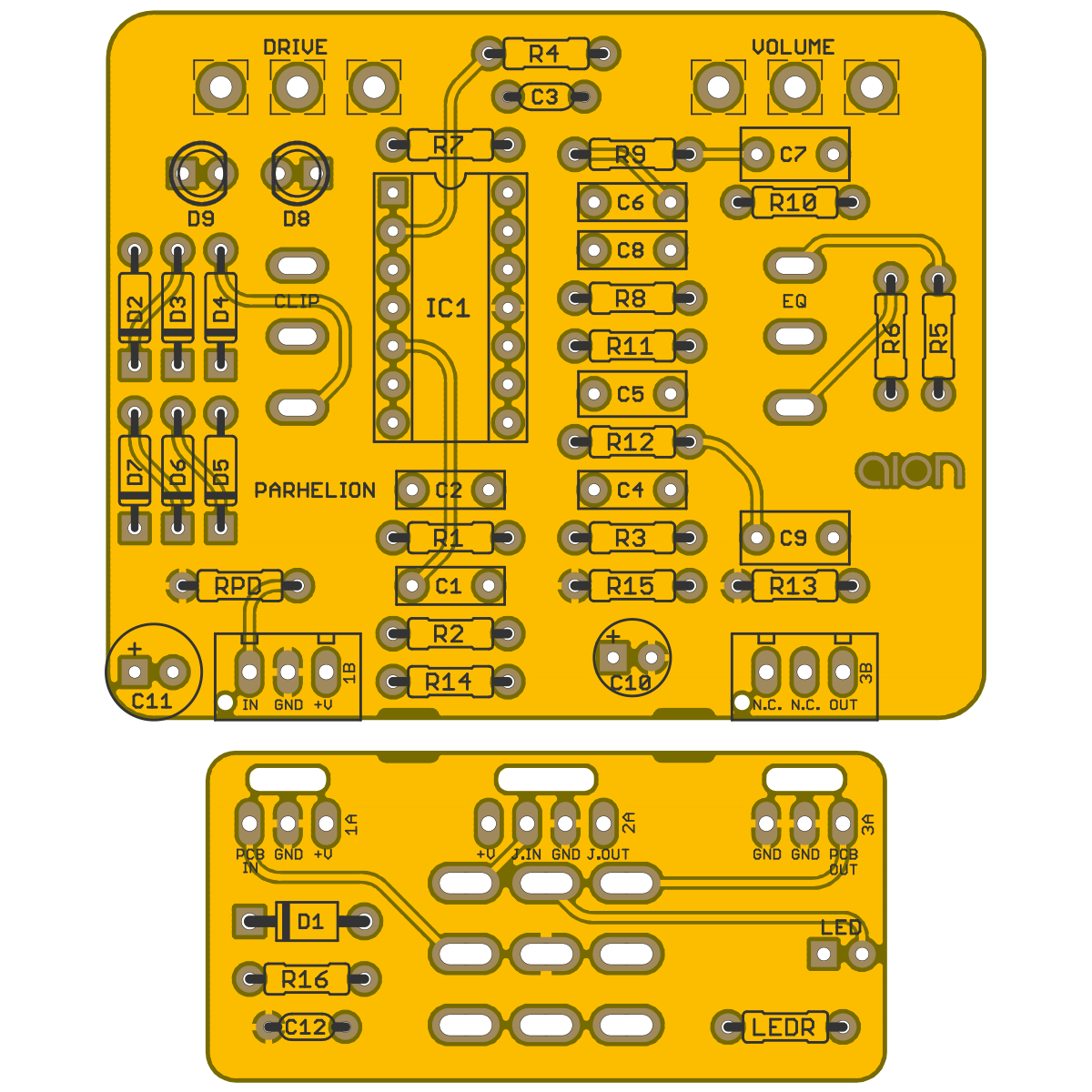
Parhelion Vintage Overdrive / BOSS® OD-1 Overdrive
A precursor to the Tube Screamer known for being the first overdrive effect to utilize diodes in a negative-feedback arrangement for clipping purposes.
aionfx.com
dot matrix madness
Active member
Phonopreamp. By far better harmonic distortions than the TL074.
Feral Feline
Well-known member
Something along the lines of hifi, such as an EQ or compressor or preamp — waste of the chip if used for a dirt circuit. YMMV
dot matrix madness
Active member
Definitely. TL074 is general purpose, NE5532 (dual OpAmp) is Hifi, OPA4134 is HighEnd.Something along the lines of hifi, such as an EQ or compressor or preamp — waste of the chip if used for a dirt circuit. YMMV
nooneknows
Member
OPA2134 is SUPPOSED to be superior, but the distortion profile of the NE5532 is still better, old but gold
Something along the lines of hifi, such as an EQ or compressor or preamp — waste of the chip if used for a dirt circuit. YMMV
Yeah that's a good point. I'll do some digging
Thanks for the suggestions everyone
drew.spriggs
Well-known member
Just a single chip? I've got gerbers for a 6 band with footswitchable boost that loves fancy ICs.Yeah that's a good point. I'll do some digging
Thanks for the suggestions everyone
I really do agree using high slew rate ICs for clipping doesn't sound that great
Just a single chip? I've got gerbers for a 6 band with footswitchable boost that loves fancy ICs.
I really do agree using high slew rate ICs for clipping doesn't sound that great
Yeah just the one quad but I've got a tube of duos. I'd be interested in that gerber mate
drew.spriggs
Well-known member
No problem - I did have separate switching PCBs for it, but I'll do some rejigging to get everything onto a single PCB so they're easier to get made.Yeah just the one quad but I've got a tube of duos. I'd be interested in that gerber mate
The first version I made did need an 18v supply, but I've changed over to an isolated DC-DC converter to make them way easier to power.
Cool mate sounds good. I've been messing around in Diptrace with charge pumps and such this week. Will be putting in an order in with JLBPCB in a day or two. I'm new to PCB design and I've been quite ambitious so far lol. Will see how that goesNo problem - I did have separate switching PCBs for it, but I'll do some rejigging to get everything onto a single PCB so they're easier to get made.
The first version I made did need an 18v supply, but I've changed over to an isolated DC-DC converter to make them way easier to power.
drew.spriggs
Well-known member
Just letting you know I haven't forgotten - I've redesigned the board for an onboard isolated +/-15v power supply (that actually meets EMC class B regulation), and redoing the layout to reduce the noise floor even further (it was already pretty good on the original, but I reckon I can get lower). There is 1x SMD inductor on board, but it's pretty big and a real easy to hand solder.Cool mate sounds good. I've been messing around in Diptrace with charge pumps and such this week. Will be putting in an order in with JLBPCB in a day or two. I'm new to PCB design and I've been quite ambitious so far lol. Will see how that goes
I moved all the groupings of filters around to optimise the layout as much as possible, so we should be able to get this thing perfect. You also have the ability to change your filter centers/Q pretty easily - I've got octaves from 80hz and matching Q's all the way up the board, but you might want something a little different.
Cheers
That sounds amazing @drew.spriggs thank you!
drew.spriggs
Well-known member
Just letting you know I haven't forgotten - I've redesigned the board for an onboard isolated +/-15v power supply (that actually meets EMC class B regulation), and redoing the layout to reduce the noise floor even further (it was already pretty good on the original, but I reckon I can get lower). There is 1x SMD inductor on board, but it's pretty big and a real easy to hand solder.
I moved all the groupings of filters around to optimise the layout as much as possible, so we should be able to get this thing perfect. You also have the ability to change your filter centers/Q pretty easily - I've got octaves from 80hz and matching Q's all the way up the board, but you might want something a little different.
Cheers


Almost done - just need to finalise a few things to make it as easy/cheap to make as possible. Using a fully isolated onboard switcher to get +/-15v rails, and I've included all the components to meet EMI requirements - there are a couple of SMD components required, but all very easy ones to hand solder. I was originally going to have the boards stackable with pin headers to connect them, but I think I'll go back to my normal ribbon cables as they make the entire thing smaller (and IIRC I think the whole fab cost comes down a little bit).
@drew.spriggs wow mate that looks fabulous
drew.spriggs
Well-known member
Finished.


I've added the PCBWay direct output and a BOM - everything is pretty straight forward and easily available. It does require a DC-DC converter (which I moved onto the switching PCB to massively reduce the radiated noise potential), and if you grab the datasheet for it the recommended cap/inductor to meet EMI spec is listed.
I have built the EQ section before and it worked great, but the power board is untested. I've had a couple of people look over it to check I haven't missed anything and I think we're good, but no guarantees are given/etc. The only change I'm going to make is to use a couple of SMD quad opamps with an adaptor, and have SMD decoupling on the back of those adapter boards.
The only thing I would be mindful of while building is cutting component leads short once soldered to ensure they're not shorting on the back 9mm pot leg (you can just cut this off if you want too).
@drew.spriggs ah mate I didn't thank you for this - got sidetracked
Looks wicked. I'll be putting an order in for more PCBs next week so I'll tack it on
Just testing some stuff now. Might be able to return the favour all being well
Looks wicked. I'll be putting an order in for more PCBs next week so I'll tack it on
Just testing some stuff now. Might be able to return the favour all being well
andrewsrea
Well-known member
That chip is great for anything you want uncolored / low distortion.
Similar threads
- Replies
- 10
- Views
- 2K
- Replies
- 13
- Views
- 2K