It started off so innocently... I liked using my Tommy III and MDMA pedals together so much that I wanted to put them in the same enclosure with an order switch. I figured, hey in addition to each effect's own stomp switch, why not have a third one in the middle so I can easily bypass them both at the same time. Both circuits were working great built into their own enclosures before I attempted combining them.
TL;DR the effects aren't activating at all and the master switch in the middle often mutes the signal. I imagine it's a wiring issue, but I'm way too easily confused by all the switch wiring to wrap my head around what's up.
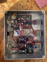
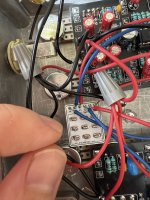
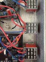
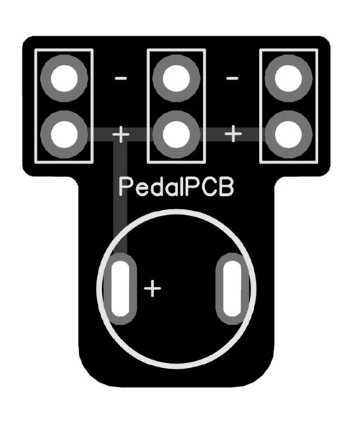
I grabbed one 3PDT order switch breakout board and three 3PDT breakout board. This is how I Frankensteined the dual circuit enclosure:
First, the individual circuits. At no point do either of the effects sound like they're on. In fact, each circuit sounds like it's bypassed when its LED indicator light is on. Twiddling their knobs does nothing, the order switch seems to do nothing.
Second, LEDs for the individual circuits will *only* turn on when master switch is set to on (LED lit up). In many scenarios, when I then turn that master switch off, it kills *all* signal. So what I expected is signal would pass through when that switch is off, like in a conventional pedal build. Instead it only lets signal pass when it's on, and mutes all sound when off. There are exceptions to this! If no signal is coming through, toggling the stomp switch on one of the circuits will unmute the sound, even though that circuit's LED remains off.
I'm just straight up scratching my head over this one. Any insight would be incredible.
TL;DR the effects aren't activating at all and the master switch in the middle often mutes the signal. I imagine it's a wiring issue, but I'm way too easily confused by all the switch wiring to wrap my head around what's up.
I grabbed one 3PDT order switch breakout board and three 3PDT breakout board. This is how I Frankensteined the dual circuit enclosure:
- Wired each circuit to its own footswitch, each with using a 3PDT breakout board.
- Wired up the two circuits's breakout boards to the 3PDT order switch PCB as shown on the wiki.
- Wired the "in" and "out" from the order switch PCB to the "in" and "out" through holes of the 3PDT breakout board attached to the master bypass 3PDT switch.
- Wired the 1/4" jacks to the master bypass breakout board.
- Wired the master bypass breakout board's "SW" through hole to the positive lead on the DC jack.
- Wired the anode of the LED to the "SW" through hole on the master bypass board and the cathode directly to the negative lead on the DC jack.
- Ran positive and negative from the DC jack to their respective through holes on each circuit.
- Ran a unified ground between the jacks, the circuits, and the master bypass switch.
First, the individual circuits. At no point do either of the effects sound like they're on. In fact, each circuit sounds like it's bypassed when its LED indicator light is on. Twiddling their knobs does nothing, the order switch seems to do nothing.
Second, LEDs for the individual circuits will *only* turn on when master switch is set to on (LED lit up). In many scenarios, when I then turn that master switch off, it kills *all* signal. So what I expected is signal would pass through when that switch is off, like in a conventional pedal build. Instead it only lets signal pass when it's on, and mutes all sound when off. There are exceptions to this! If no signal is coming through, toggling the stomp switch on one of the circuits will unmute the sound, even though that circuit's LED remains off.
I'm just straight up scratching my head over this one. Any insight would be incredible.
Last edited:


