DyeNaturally
New member
So beginner builder here. Have 3 completed circuits under my belt. The El Sol is only one with correct sound, and I have no troubles with really. Sounds great actually.
my carbon Black fuzz is another thread….makes sound but no fuzz.
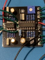
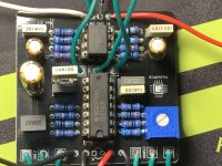
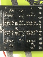
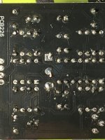
this thread is for my park and ride. I can’t get any sound from this.
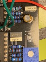
I socketed some capacitors since I didn’t have the right ones. I did use close values to the missing ones but not exact.
otherwise this is the only build I can’t get any sound out of.
Hoping to get some newbie tips for figuring this out. Not entirely sure on the correct testing procedures, I was getting voltage from input to output. And did a few other tests I seen on another thread, and seemed to be getting some voltage threw.
Could it be bad ic’s?? Ones were from tayda. Other China eBay people.
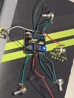
Also got the wrong pots(solder posts not pcb threw) and have them wired to the pcb, why so many wires coming off it. But should be fine if the wires correlate to the pins???
thanks
I just swapped the ic’s and still nothing.
Thanks for helping a newbie.
my carbon Black fuzz is another thread….makes sound but no fuzz.
this thread is for my park and ride. I can’t get any sound from this.
I socketed some capacitors since I didn’t have the right ones. I did use close values to the missing ones but not exact.
otherwise this is the only build I can’t get any sound out of.
Hoping to get some newbie tips for figuring this out. Not entirely sure on the correct testing procedures, I was getting voltage from input to output. And did a few other tests I seen on another thread, and seemed to be getting some voltage threw.
Could it be bad ic’s?? Ones were from tayda. Other China eBay people.
Also got the wrong pots(solder posts not pcb threw) and have them wired to the pcb, why so many wires coming off it. But should be fine if the wires correlate to the pins???
thanks
I just swapped the ic’s and still nothing.
Thanks for helping a newbie.