PCB RFC - Grindhaus Fuzz

leadfoot

Well-known member
After seeing the DOD Grindhaus Fuzz show up in the wish list section and reading up on it and figured I'd make a version of it.

I based it off of the Hype Fuzz from FuzzDog, tossed in the Big Muff tone stack (with the ability to bypass), and then the make up boost as seen in the DOD Grindhaus documentation.

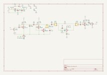
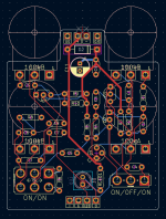
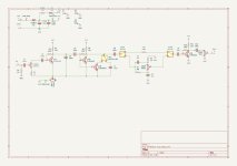
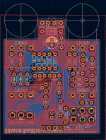
I've attached the schematic circuit and the pcb routing and would like feedback on how to make it better. I'll be using a ground pour on front and back to handle the grounds. When it is all done, I'm using the mad bean suggested trace sizes for power and signal.

I'll be happy to share the gerbers so others can make it as well.

Thanks!

Schematic:
Grindhaus Fuzz - Schematic.jpg

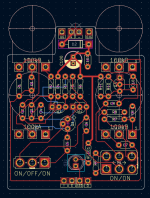
PCB:

grindhaus-fuzz-pcb.png
 
Nice! I'm no expert so take all of this with a grain of salt. I also mostly route SMD layouts but I think most of the advice will hold.
Some specific feedback:

- Kicad's default track width is soooo smol. Even with SMD components I try to keep my trace width at 0.5mm instead of the default of 0.2mm.
- Try to avoid routing back side if you can. The less stuff you have on the back, the better your ground pour. I see a few places where you're routing on the back where you probably don't need to.
- Don't be afraid of routing longer than you need to, even routing around the outside edge to avoid crossing. I've found that it works well for me to route 9V or VREF around the outside edges since that often needs connections on various places around the board.
- For example pin2 of upper left pot could go all the way around the outside to output to avoid crossing thru the middle of the board.
- Likewise for the input.
- (And it almost feels like the input half and output half want to be switched, since the output comes in on the right but is controlled by the left pot, and vice-versa. Maybe not that big of a deal but then you potentially have more crosstalk)
- C11 is near, but not on, the center line of the board (eye twitch)
- For the silkscreening, it can be nice to have the component value visible after population so you don't need to bring a map when you are trying to diagnose something. But I do see a lot of through-hole designs like this.
 
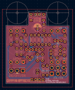
Looks good! The back will be a lot less broken up now. You might be able to spread the top row of resistors apart just a tad to get another trace or two between them rather than on the back. But maybe gilding the lily here.

One thing I notice that some people will point out is the 90 degree bends in the traces. If you were to get this reviewed on Reddit or something at least one person would have a stroke. The '45 degree angles only' is mostly a holdover from less refined etching processes, nowadays that is less of an issue, but it does violate 'best practices'. Also at higher frequency the 90-degree plus bends can actually cause more reflections/echos but I don't think it matters at audio frequencies. I still don't really know what to do about T/Y junctions myself though.

A tip I kind of recently learned in KiCad is the 'D' hotkey for 'drag'. You can grab a section of track and drag it around to make the angles more smooth. You can also set the router to 'push' so if you run into another track while dragging you push it instead of crossing it. There's also 'break track' which might only be in the right-click menu that you can use to create a joint in a track so you can drag the segment you just broke off. The 'D' key works on components, too. It will drag it along with tracks that are connected to the pads. Nice if you're moving things fairly small distances so you don't have to re-route. Like when you drag C11, Q1, Q2, Q3 and C5 to make them symmetric down the center line. (eye twitch) ;-)

Oh one more thing, don't forget to put some silkscreened text on there with your name/brand and a board revision number. Fact of life, you'll probably have more than one revision of this and when you dig it out of a drawer in a year you'll want to know if it's the one that works or not before you build it out. :-)
 
Thanks again! KiCAD is definitely a learning curve from EasyEDA where I used to make my PCBs. I'll probably clean up the routes again cause I'm not super happy with the ground pours and the way Q4 worked out.

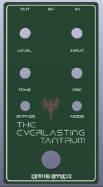
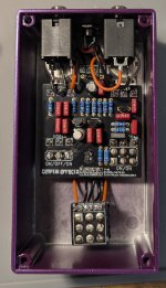
I'll throw a name on everything along with a revision.. I'm thinking "The Everlasting Tantrum" is a good name for the pcb.
 
Back
Top