
Hello,
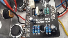
i´ve build the Ash Device from PCBGM but unfortunately the pedal doesn´t work neither when it´s activated nor when i turn it off. The status LED is activated when i push the footswitch but i can´t hear anything. It´s completly quiet. When i turn the pedal off i can´t hear any guitar, too. I have already checked the polarity of the capacitors and semicondoctors and they are fine. My suggestion is that i made any mistakes with the wiring. Can you please help me with the wiring?
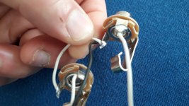
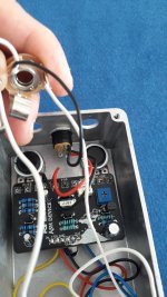
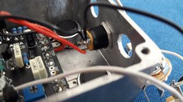
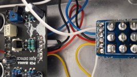
The wiring is based on the schematics from pcbgm. I connected the sleeves of both jacks with each other and then i connected the sleeve of the output jack with the negative pin of the dc jack and last i connected the negative pin of the dc jack with the solder lug on the on the circuit board (on the left, next to the soldering eye for the phase).
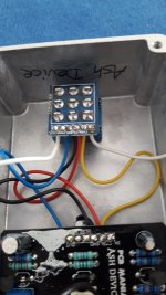
The trim pot on the pcb is set to the middle position.
i´ve build the Ash Device from PCBGM but unfortunately the pedal doesn´t work neither when it´s activated nor when i turn it off. The status LED is activated when i push the footswitch but i can´t hear anything. It´s completly quiet. When i turn the pedal off i can´t hear any guitar, too. I have already checked the polarity of the capacitors and semicondoctors and they are fine. My suggestion is that i made any mistakes with the wiring. Can you please help me with the wiring?
The wiring is based on the schematics from pcbgm. I connected the sleeves of both jacks with each other and then i connected the sleeve of the output jack with the negative pin of the dc jack and last i connected the negative pin of the dc jack with the solder lug on the on the circuit board (on the left, next to the soldering eye for the phase).
The trim pot on the pcb is set to the middle position.
Attachments
-
Ash-Device-Building-Docs-1.pdf362.1 KB · Views: 6
-
Pedal-Wiring-Guide-1.pdf911.5 KB · Views: 4
-
 20230919_113428.jpg385 KB · Views: 14
 -
 20230919_113538.jpg331.4 KB · Views: 15
 -
 20230919_113615.jpg274.1 KB · Views: 15
 -
 20230919_113819.jpg324.9 KB · Views: 16
 -
 20230919_113832.jpg265.9 KB · Views: 16
 -
 20230919_113843.jpg276 KB · Views: 18
 -
 20230919_114024.jpg288.2 KB · Views: 18
 -
 20230919_114032.jpg335.3 KB · Views: 18
