Pedalpcb Daughterboard wiring with Huntington Audio Fuzz Face PCB

Manischewitz_Papi

New member
So I'm about ten pedals deep into building since diving into all this last summer, and as such to date I've always used 3PDT daughterboards (Fuzzdog and PPCB, respectively) in my builds. Recently, I ordered a little part tester kit from Huntington Audio and got this dope little freebie Fuzz Face PCB in the mail with it.

I successfully assembled an NPN Dallas Arbiter silicon FF, as I was able to validate via my Fuzzdog Simple Tester, but my question is: what do I solder to the Footswitch hole on the PPCB daughterboard?

IMG_20250209_004457051.jpg

Thanks in advance! And apologies for my potato-ass phone camera.
 
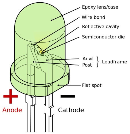
Just to add (while it might have been obvious), the SW goes to the Current Limiting Resistor, which goes to the LED, which then goes to the 9V supply (so the same place the battery + comes from).

The power LED is not really a part of the pedal circuit, it's just hanging there by the side to let you know when the pedal is active - it's often included on the PCB's just for ease of use, but it doesn't interact with the pedal itself.
 
Also...
I've noticed that the CLR always seems to be wired directly to the power source, and never comes off the filtered power of the circuit itself.

The PCB usually gets some filtering with a 47µ or 100µ to ground:

9V > Polarity Protection > Power-Filtering > Circuit​
⬇︎​
CLR > Bypass-LED​

Never in parallel to the circuit like this:

9v > Polarity Protection > Power-Filtering > CLR > Bypass LED​
⬇︎​
9v > Polarity Protection > Power-Filtering > Circuit​

I'm guessing it's to help prevent noise/popping from sneaking into the audio-path (though popping can happen engaging the pedal anyway).
I never see the bypass-LED being powered otherwise. Makes sense, especially if you're using a charge-pump to not have to use a huge CLR to bring current down from 12v/18v/24v just for the bypass LED.

Might have a play around with that on the breadboard, stick the CLR after the polarity-protection and power-filtering next to the main circuit...
 
The only dumb question is the one that exists but doesn't get asked.

In a boardless scenario it doesn't matter where you stick the CLR, so long as there is resistance at some point in the LED-Bypass Circuit — the CLR could be on the anode or kathode, to reiterate — just so long as there is some resistance, otherwise POOF! .


On the majority of PedalPCB boards the "SW" goes to the Kathode of the LED, the LED's Anode then goes to the CLR which is connected to +9V.

The circuit is open until you hit the footswitch, which closes the connection between lug 4 (SW) and lug 5 (GND) and completes the circuit — power can now flow through the CLR & LED.


There are ample examples of diagrams online of 3PDT bypass wiring schemes, fire up a search engine and you'll find many ways to wire a 3PDT to perform the same basic function, and some with extra options thrown in...

3PDT Wiring options.png
 
Manischewitz_Papi 2 IMG_20250209_004457051.jpeg


How-LEDs-Work.jpg
 
Back
Top