Hello pedalpcb community,
I would greatly appreciate some insight.
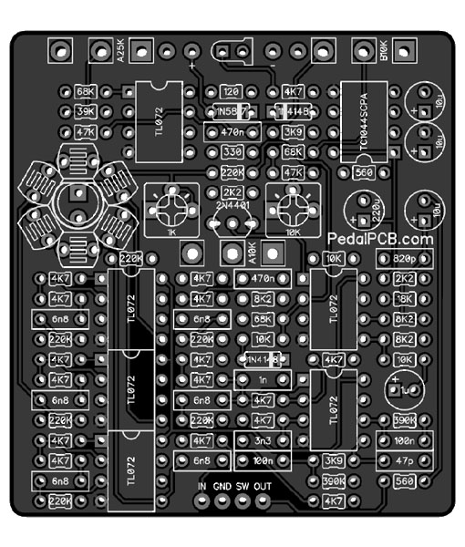
I am building the Phase ii.

 www.pedalpcb.com
It calls for KE-10720 LDR Photoresitors and a Yellow LD. I ordered all the parts per specifications in the build document but tayda was out of KE-10720.
So i ordered Photo Conductive Cell Resistor LDR 540nm RADIAL 5528.
From other threads i have gathered that the important details are the photo resistance and dark resistance which are very similar (good, i think). I have compared the manufacturing specs on both.
PR 10k to 20k. DR 0.5 M
There is some variation on rise and fall but the one that has me concerned is spectral peak.
KE-10720’s are 550 nm min to 650 nm max
https://www.taydaelectronics.com/datasheets/files/A-5795.PDF
The ones i ordered are 540 nm peak spectral value.
https://www.taydaelectronics.com/datasheets/files/A-1528-2.pdf
I note the specs are not totally aligned on how the specify that.
From what i gather 540 nm is a wavelength in the range of green. 650 nm is yellow.
I think the intent of the build is to match the sensor to the colour. What i am unsure of are other implications of swapping.
So here’s what i see my options are:
1. 3mm Yellow light with 540 nm LDRs
2. 5mm Green light with 540 nm LDRs
3. Order LDR’s from mouser for $20 + $30 shipping and get divorced.
I like my wife. I think option 2 is the way to go. And rely on the trim pots to dial it in.
I humbly request someone who understands this stuff to tell me the best approach. I dont want to go through all the effort of building this to cheap out and have it not sound good and sit on shelf instead of my board.
i have 5 mm green LED’s and 3 mm yellows. Does it matter for the lamp if its 3mm or 5 mm? I can get LED’s easy enough if it matters.
Please help. Thank you,
Jer
I would greatly appreciate some insight.
I am building the Phase ii.

Phase II - PedalPCB.com
Compare to Mu-Tron Phasor II
It calls for KE-10720 LDR Photoresitors and a Yellow LD. I ordered all the parts per specifications in the build document but tayda was out of KE-10720.
So i ordered Photo Conductive Cell Resistor LDR 540nm RADIAL 5528.
From other threads i have gathered that the important details are the photo resistance and dark resistance which are very similar (good, i think). I have compared the manufacturing specs on both.
PR 10k to 20k. DR 0.5 M
There is some variation on rise and fall but the one that has me concerned is spectral peak.
KE-10720’s are 550 nm min to 650 nm max
https://www.taydaelectronics.com/datasheets/files/A-5795.PDF
The ones i ordered are 540 nm peak spectral value.
https://www.taydaelectronics.com/datasheets/files/A-1528-2.pdf
I note the specs are not totally aligned on how the specify that.
From what i gather 540 nm is a wavelength in the range of green. 650 nm is yellow.
I think the intent of the build is to match the sensor to the colour. What i am unsure of are other implications of swapping.
So here’s what i see my options are:
1. 3mm Yellow light with 540 nm LDRs
2. 5mm Green light with 540 nm LDRs
3. Order LDR’s from mouser for $20 + $30 shipping and get divorced.
I like my wife. I think option 2 is the way to go. And rely on the trim pots to dial it in.
I humbly request someone who understands this stuff to tell me the best approach. I dont want to go through all the effort of building this to cheap out and have it not sound good and sit on shelf instead of my board.
i have 5 mm green LED’s and 3 mm yellows. Does it matter for the lamp if its 3mm or 5 mm? I can get LED’s easy enough if it matters.
Please help. Thank you,
Jer
