Tayda KE-10720 LDR very out of spec. 50 ohms bright, 2 Meg dark! (Solved)

allanshookphoto

New member
Just received my order of a dozen KE-10720 LDR's from Tayda, and they are supposed to be 10k/20k light and 500k dark. These ones measure less than 50 ohms light and over 2Meg dark. That is so far out of specification, very disappointed.
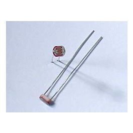
These are the ones I ordered:
IMG_0622.jpg
So, does anyone have a source for KE-10721's or equivalents. I have read about a dozen posts in this forum about KE-10720's, and the general consensus is to get these ones form Tayda.
 
I could be wrong, but I’m pretty sure the stated specs are minimum values. At most, 10K light, at minimum 500K dark
OK. So, at 10 Lux, (if I can get exactly 10 Lux of brightness from my LED's) these should measure 10kohms to 20kohms, but if I shine 100+ Lux on them the resistance will just keep going down, to less than 50 ohms? And, in absolute darkness, the minimum amount of resistance would be 500Kohms , but it could go as much as 2Mohms (or more) resistance? There is no "maximum" amount of resistance in the dark?
I'm just trying to get the logic straight in my head. It seems the real trick then, is to get the LED at the right brightness (and darkness), and the right distance/angle from the LDR so that I'm getting the lower and upper resistance values the circuit needs to sound right. It might not be advisable to get the "Super Bright" LED's then, as they might be shining way more than 10Lux on the LDR's at full brightness, giving values of way less than 10K (if that is what the circuit actually wants).

Thanks!

(I'm building an Abyss and a Pendulum)

KE-10720 spec.jpg
 
OK. So, at 10 Lux, (if I can get exactly 10 Lux of brightness from my LED's) these should measure 10kohms to 20kohms, but if I shine 100+ Lux on them the resistance will just keep going down, to less than 50 ohms? And, in absolute darkness, the minimum amount of resistance would be 500Kohms , but it could go as much as 2Mohms (or more) resistance? There is no "maximum" amount of resistance in the dark?
I'm just trying to get the logic straight in my head. It seems the real trick then, is to get the LED at the right brightness (and darkness), and the right distance/angle from the LDR so that I'm getting the lower and upper resistance values the circuit needs to sound right. It might not be advisable to get the "Super Bright" LED's then, as they might be shining way more than 10Lux on the LDR's at full brightness, giving values of way less than 10K (if that is what the circuit actually wants).

Thanks!

(I'm building an Abyss and a Pendulum)

View attachment 56414
I think there’s a way to accomplish what you’re after. I seem to recall seeing it when looking into using photoresistors for another project. I’ll poke around a little tomorrow morning to see if i can find what I think it is you’re looking for.
 
OK. So, at 10 Lux, (if I can get exactly 10 Lux of brightness from my LED's) these should measure 10kohms to 20kohms, but if I shine 100+ Lux on them the resistance will just keep going down, to less than 50 ohms? And, in absolute darkness, the minimum amount of resistance would be 500Kohms , but it could go as much as 2Mohms (or more) resistance? There is no "maximum" amount of resistance in the dark?
I'm just trying to get the logic straight in my head. It seems the real trick then, is to get the LED at the right brightness (and darkness), and the right distance/angle from the LDR so that I'm getting the lower and upper resistance values the circuit needs to sound right. It might not be advisable to get the "Super Bright" LED's then, as they might be shining way more than 10Lux on the LDR's at full brightness, giving values of way less than 10K (if that is what the circuit actually wants).

Thanks!

(I'm building an Abyss and a Pendulum)

View attachment 56414
Check this video out, I think this may help some:
 
  • Like
Reactions: spi
I tore down my Abyss last night to swap the LDRs. I used the same tayda ke-10720s I used originally, but I oriented them differently.

Original install:

63ADED6A-6D01-436D-98AE-89B25623686E.jpeg

Final setting I went with:

A4C66276-181C-46E8-8C0A-085F4A4DB310.jpeg

The way I had them mostly laying down originally, the pedal functioned fine, but it cut out a lot of the bass frequencies. Kind of a cool lo-fi sound, but definitely wasn’t “right”.

I put in the new set standing up roughly in the middle of the LED height-wise, and initially set them in contact with the LED. This brought all the bass back, but the pedal would distort and lose the modulation if I cranked up the voice / level knobs.

Adding the gap cleared up most of the distortion. I still get a little at max voice, but the vibe effect is still there. I probably could have pulled them back a little further, but I decided to call it good for now.
 
I tore down my Abyss last night to swap the LDRs. I used the same tayda ke-10720s I used originally, but I oriented them differently.

Original install:

View attachment 56433

Final setting I went with:

View attachment 56434

The way I had them mostly laying down originally, the pedal functioned fine, but it cut out a lot of the bass frequencies. Kind of a cool lo-fi sound, but definitely wasn’t “right”.

I put in the new set standing up roughly in the middle of the LED height-wise, and initially set them in contact with the LED. This brought all the bass back, but the pedal would distort and lose the modulation if I cranked up the voice / level knobs.

Adding the gap cleared up most of the distortion. I still get a little at max voice, but the vibe effect is still there. I probably could have pulled them back a little further, but I decided to call it good for now.
Great info, Thanks! This has me thinking about a few other points.

I'm building a Pendulum and an Abyss. In the pendulum, the audio signal actually goes through the LDR's and they act exactly like a potentiometer in that situation. There is a 1K resistor in series after them, so that sets the low resistance limit (max brightness/lowest resistance/highest volume), and several Megs will be upper resistance (max darkness/highest resistance/volume basically off). So, originally I thought I wanted to get the brightest LED's I could find, but maybe that isn't necessary, or even desirable. If a 3mm diffused 30mcd LED gets bright enough to get the LDR below 1Kohm, then a 1200mcd LED will be overkill and not work any better. A 30mcd and 1200mcd LED both get equally as dark.

Now, the Abyss uses the LDR's as the bias of the four op-amp all-pass filter stages (if I'm using the correct terminology). The brightness of the LED, and the angle/proximity of the LDR's to the LED achieve a very different function in that arrangement. If the LDR's see too much light, and their resistance goes too low, the bias/volume of the filter stages change (maybe too loud), and you get distortion. So, once again, maybe the super-bright 3mm diffused yellow LED's I chose might actually be too bright? I don't know yet.

I think the MCD ratings of the LED's might actually be a good thing to know, and the beam angle (40°, 60°, or 90°), as well as other parameters.

Thanks everyone!
 
I think all the abyss build reports I could find used a 5mm diffused yellow, and that’s what’s specified on the BOM so that’s what I went with. As sensitive as that ldr arrangement seems to be, I’d recommend something similar.

You’ve already gone above my pay grade on the analysis, but if you’re looking to go off the deep end on LDRs, the rate they switch at is also different between the various available models, and might be a factor in some circuits.

Post in thread 'Delegate (Warden) Upgrades'
https://forum.pedalpcb.com/threads/delegate-warden-upgrades.3044/post-195498

And I actually made the same mistake on the Sproing Deluxe tremolo that I made on the abyss.

Thread 'Sproing deluxe in DIY box'
https://forum.pedalpcb.com/threads/sproing-deluxe-in-diy-box.17449/
 
Yes, I have a 5mm diffused yellow LED for the Abyss. I know the ones on Tayda are supposed to be 2000 to 3000 MCD, and the ones I sourced on DigiKey are 1200 MCD. Maybe if mine are just a touch "dimmer" it might not lower the LDR's resistance too much, if that is what causes the distortion in the circuit.

Sometimes, there is a fine line between knowing what I need to know to make the right choice, and going off the deep end of analysis.

Cheers!
 
Back
Top