POLYHOG don't work ! > ? <

KWE

New member
Hello,
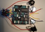
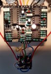
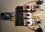
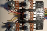
Concerning the PolyHog ; mine don’t work . I am a long-time intermediate builder , and this is the first box that has not worked for me . I have checked everything thrice and can’t find a flaw . I was wondering if others have had problems with this build . Is the PCB wrong somewhere? Or, maybe one of the components is defective . I bought the complete kit at Musikding in Germany . I would appreciate hearing if difficulties have been suffered by others , and if a cause (or causes) is known.
Thank you , KWE
 
There has been a few errors with components in those kits recently 1M resistors labelled as 1K, 100 ohm trimmers labelled as 100K etc

You're better posting some pictures of your build so we can clearly see both sides of the board and trace your offboard wiring

First thing I'd check is that R1's a 1K and not a 1M
 
Last edited:
Hello again,
I am still trying to get my PolyHog working. I cannot find the error. I am beginning to think there is a defective component.
As can be seen in the included photo of my checklist, I have determined that all of the components are placed correctly, including values and polarities. I have checked the solder points and made sure that there are no solder-overruns, and that no component-legs are touching where they shouldn't.
I would appreciate it if an advanced builder would have a look at the photos and report obvious errors or suspicions.
My suspicion 1: The Q1 supplied with the kit is marked J2 01-07. Is that OK?
My suspicion 2: C13 looks like it might have overheated during soldering.
My question 1: The online Wiring Diagram shows the 3PDT connecting GND to SW on the PCB in the pedal-ON-mode , and GND to IN on the PCB in the pedal-OFF-mode. Are these correct? What are the purposes of these? I have included here a photo of what I am referring to.
Thanks very much, KWE 01-PolyHog Guts-A1.jpg
 

Attachments

  • 02-PolyHog Guts-A2.jpg
    02-PolyHog Guts-A2.jpg
    219.5 KB · Views: 12
  • 03-PolyHog Guts-A3.jpg
    03-PolyHog Guts-A3.jpg
    268.5 KB · Views: 13
  • 04-PolyHog Guts-B1.jpg
    04-PolyHog Guts-B1.jpg
    236.8 KB · Views: 13
  • 05-PolyHog Guts-B2.jpg
    05-PolyHog Guts-B2.jpg
    477.5 KB · Views: 11
  • 06-PolyHog Checklist.jpg
    06-PolyHog Checklist.jpg
    248 KB · Views: 10
  • 07-PolyHog PCB to 3PDT Question.JPG
    07-PolyHog PCB to 3PDT Question.JPG
    69.6 KB · Views: 10
The wiring diagram is correct. In “ON” mode, the sw pad connects to ground to complete the LED circuit. In “OFF” mode, the pcb input is grounded. This is not strictly necessary, but is generally considered best practice to avoid any possibility of noise or oscillation from bleeding through to the bypass signal in “OFF” mode.

For J201s I prefer to use smd with an adapter board.

The through hole package J201s are harder To find these days, and there are many fakes out there. If your’s came in a kit, I would hope they sourced it from a good place, but I can’t say for sure.

Have you used an audio probe before? I would recommend wiring one up (just google it, they’re pretty simple). Then you can check for sound at various points by following the circuit diagram.
 
The Solder side of PCB Board needs to be cleaned with Isopryl or Electrical Spray Cleaner & Component side around +, - , LED connections!

Check Matching colours for Continuity :
Polyhog Continuity Test.jpg
 
Some of your 3PDT and the DC jack solder joints look ball like and could be dry inside I'd remove some of the solder from the 3PDT the DC jack looks a bit like the solder joints haven't flowed very well

You haven't told us if you're getting power to the board or bypass signal that would help identify whether the problem's with your wiring or a fault in the circuit let us know what power you get to the + on the pcb

We'd then know the DC jack solder joints are ok or not

If you get bypass signal that tells us the jacks are ok for that throw of the switch (bypass)

We can then advise what to detail next e.g. IC voltages and so on

I checked all the values on your pcb they all look correct and are correctly orientated I couldn't see R13, 14, 16 fully
 
Last edited:
Back
Top