Pro-10 switch popping

Locrian99

Well-known member
Yay another switch popping thread. Anyways looking for thoughts here.

Switch popping on both green and blue sides.
It is worse the higher the signal, both gain knob and volume increase it.

I’ve built several of these and don’t recall having the issue, but also the volume does need to be up a bit before it shows up to we’ll call them annoying levels. Rapidly pushing the switch seems to cause it to diminish, then it comes back. During the rapid switching, no pause. The rapid switching effecting it seems capacitor related to me.

Tried the amz resistor and cap from led, no change.
Reflowed all solder joints no change.
Swapped from daiertek 3pdt to sbp 3pdt pro 1kg no change
Removed LED from blue side no change to blue side
Replaced blue side 4u7 electro output cap with a 1u tant, no change
Next up is trying a 1u film cap.


I looked at the mr. Black switch popping article. And may try the resistor cap in series on the input as he describe, but not sure of where to start in value. Sounds like 1M is good place to start for resistor but for cap? Looks like youd run tthese from the circuit in pad on the 3pdt board to the effect in (unless theres a better way I’m not thinking of).

Anyways any ideas appreciated
 
Try a 2.2M resistor on the input jack simply between the hot and ground lug. Aside from that, I find that occasionally I get a batch of 3DPT stomp switches that are internally glitchy transitions, which causes pops.
 
Try a 2.2M resistor on the input jack simply between the hot and ground lug. Aside from that, I find that occasionally I get a batch of 3DPT stomp switches that are internally glitchy transitions, which causes pops.
I hadnt tried on the input. I did try a 2M from the output pad to leg 1 of the blue side volume pot and it made it better for the blue, was going to try the output of green side to ground but i can try the input.
 
Try a 2.2M resistor on the input jack simply between the hot and ground lug. Aside from that, I find that occasionally I get a batch of 3DPT stomp switches that are internally glitchy transitions, which causes pops.
Tried this, and several other things no luck.

I have a 2nd board. Im going to build it and see if I still have the issue. Im assuming I will but at this point im willing to try anything lol.
 
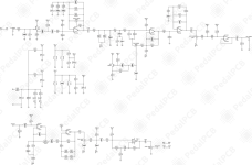
Looking at the schematic of the pro 10, it looks to me like the green side is missing an input cap. I’m wondering if this is part of the issue. As I’m not the first one to mention switch pop on this circuit.

If the original used a different switching system and this is a direct clone I wonder if this is an issue. https___forum.pedalpcb.com_attachments_schematic-pro10-png.27671_.png
 
Looking at the schematic of the pro 10, it looks to me like the green side is missing an input cap.

Good catch!

With as many ODRs I've built, I never caught this.

The original ODR-1 did not have an input cap, because it used FET flip-flop switching + buffers for the bypass (as in, not true by-pass). So it didn't need it. Accordingly, and depending on how that first FET is biased (referenced to ground via 1M), there is probably 0.3V to 1.5V on the switch contact. Which would present a DC pop when switched, order of magnitude stronger than a guitar signal and amplified throughout the circuit. It appears that most true by-pass schematics on the internet have this condition.

A workaround would be a 100nF cap in series with R100 (33K), with a 2.2M resistor to ground on the effect input, before R100. The leak resistor will prevent a charge build-up in the cap, during the milliseconds that the switch variable contact is not touching either 'selection' contact.
 
Good catch!

With as many ODRs I've built, I never caught this.

The original ODR-1 did not have an input cap, because it used FET flip-flop switching + buffers for the bypass (as in, not true by-pass). So it didn't need it. Accordingly, and depending on how that first FET is biased (referenced to ground via 1M), there is probably 0.3V to 1.5V on the switch contact. Which would present a DC pop when switched, order of magnitude stronger than a guitar signal and amplified throughout the circuit. It appears that most true by-pass schematics on the internet have this condition.

A workaround would be a 100nF cap in series with R100 (33K), with a 2.2M resistor to ground on the effect input, before R100. The leak resistor will prevent a charge build-up in the cap, during the milliseconds that the switch variable contact is not touching either 'selection' contact.
This was kind of my current plan to try, hoping to do so tonight.
 
Good catch!

With as many ODRs I've built, I never caught this.

The original ODR-1 did not have an input cap, because it used FET flip-flop switching + buffers for the bypass (as in, not true by-pass). So it didn't need it. Accordingly, and depending on how that first FET is biased (referenced to ground via 1M), there is probably 0.3V to 1.5V on the switch contact. Which would present a DC pop when switched, order of magnitude stronger than a guitar signal and amplified throughout the circuit. It appears that most true by-pass schematics on the internet have this condition.

A workaround would be a 100nF cap in series with R100 (33K), with a 2.2M resistor to ground on the effect input, before R100. The leak resistor will prevent a charge build-up in the cap, during the milliseconds that the switch variable contact is not touching either 'selection' contact.
It would go cap, 2m2 to ground and then r100 right? Thinking best way to do this would be use the cap from switch breakout board to the effect pcb. Then just tack the resistor to ground on the backside id the pcb at the input side of r100.
 
Well i had high hopes for that one. Didn’t solve it. I am going to try a resistor in series between the switch and cap and see what that does like in the mr. Black article.

If anyone reads this and has a pro-10. Do you get switch pop at higher volume/gain settings. Like 2-3 o’clock on both
 
I have had this issue on a couple of builds which is after the last capacitor where the Resistor is going to Ground before the Out.
On the green it looks like 150k, the most common use 100k, I have had to drop it to 10k and it fixes it completely.
 
The Blue shouldn't be doing it as Level pot 2 is Out & leg 1 is going to Ground.
If you have a cold solder joint, you can get a similar pop effect when you press the footswitch on & off
If you still have an issue after changing the 150k to 10k on the green, try tapping the board while on with something firm that's not conductive to see if it pops
 
Back
Top