Propolis (Jack White Bumble Buzz)

hdansin

New member
Build Rating
5.00 star(s)
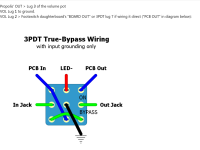
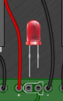
Built this one for a friend who likes Jack White. Probably one of my cleanest builds (I am still very much a novice). Went very smooth except for the LED. I don't know if it is the LED, or just me being dumb, but I had to switch the orientation. On the wiring diagram it appears the longer lead goes in the square hole, and when I tested the LED with a multimeter, the longer lead was positive, but when I powered it up the LED would not work. I had to switch it around.

It's a very cool sounding pedal. I love the octave stuff it does and I could see bringing this and not needing modulation to get gnarly. But it is very LOUD. Way higher than unity for me. I think if I had a compressor or the right drive pedal the volume jump could be tamed, thought that is speculation. Does anyone know how hard it would be to add a volume trimmer? I have a second board so I might do a volume mod on there.

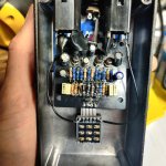
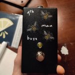
Not sure if it was strictly necessary but I added some electrical tape and a sticker on the inside to prevent shorts, since there are no pots to hold the PCB. The name is a play on Jack White's "3rd Man Hardware." I guess I am the 4th man.
 

Attachments

  • signal-2026-01-23-223503_002.jpeg
    signal-2026-01-23-223503_002.jpeg
    607.1 KB · Views: 55
  • signal-2026-01-23-223503_003.jpeg
    signal-2026-01-23-223503_003.jpeg
    439.2 KB · Views: 54
  • signal-2026-01-23-223503.jpeg
    signal-2026-01-23-223503.jpeg
    451 KB · Views: 54
Oh man. Thank you! That explains a lot. I guess I should take the wiring diagram with a grain of salt.

I love the description on the pedalpcb page. "Controls, None: Tone is in the fingers."
 

Attachments

  • Screenshot_20260124_100608.png
    Screenshot_20260124_100608.png
    29.6 KB · Views: 7
Oh man. Thank you! That explains a lot. I guess I should take the wiring diagram with a grain of salt.

I love the description on the pedalpcb page. "Controls, None: Tone is in the fingers."
Yeah, I think that generic wiring diagram in the build doc is old and still uses the old confusing LED layout that makes no sense :ROFLMAO:

Does anyone know how hard it would be to add a volume trimmer?
I'm usually a build-by-the-numbers guy, I don't usually get into mods or thinking too much about schematics, but looking at some schematics for other fuzzes in the catalog, it looks like volume usually sends some of the signal to ground somewhere at the end of the circuit.

1769268322658.png

Not sure if this is the smartest way, but seems like you could try a smaller resistor for R17 to send more signal to ground. (or insert a trimmer there).

1769268406824.png

I bought some of these trimmer adapter boards a long time ago and never used any. Now that I look at it, it seems like you might be able to just cut off the middle leg and bend the outer two out to resistor width, but I guess they are kinda short and stiff legs, so I don't know.

Might be easier to just audition some different resistors in that spot.


Attachments

  • Screenshot_20260127_093318.png
    Screenshot_20260127_093318.png
    42.3 KB · Views: 4
Thank you! I did see that thread when I was lurking about adding a volume. If I am understanding correctly, I can follow the instructions from the screenshot I've attached?

I do want to do it with a trim pot though, so I guess I should use the trimmit board to make all the connections. And it's an A100K pot? How did yours work out?
Yep, I believe I followed that and also raised R17 a bit for more overall volume at maximum. Worked great!
 
Here's how I'd approach adding a VOLUME pot to this Union Tube & Transistor circuit (White doesn't do jack himself, he simply pays others to do it for him):

Replace R17 with an A500k pot.

Lug 3 of the pot comes off the R17 pad that leads to both C9 and R16.
Lug 1 of the pot goes to the R17 pad that leads to ground (or any ground point — doesn't have to be R17's.
LUG2 goes to your bypass control, ie where the PCB's "OUT" would normally go — don't use the "OUT" of the PCB at all.


OR

Use the OUT of the PCB to go to LUG 3 of the VOLUME pot
Lug 2 VOL goes to the BYPASS
Lug 1 VOL to ground
Don't populate R17 at all.


You could also try A100k, A250k ... see what you like best.

Whoops... missed you wanted it to be a trimmer. Same-same setup, but using B100k, B250k, B500k trimmers.
 
Back
Top